Frame Assembly
Tools Required
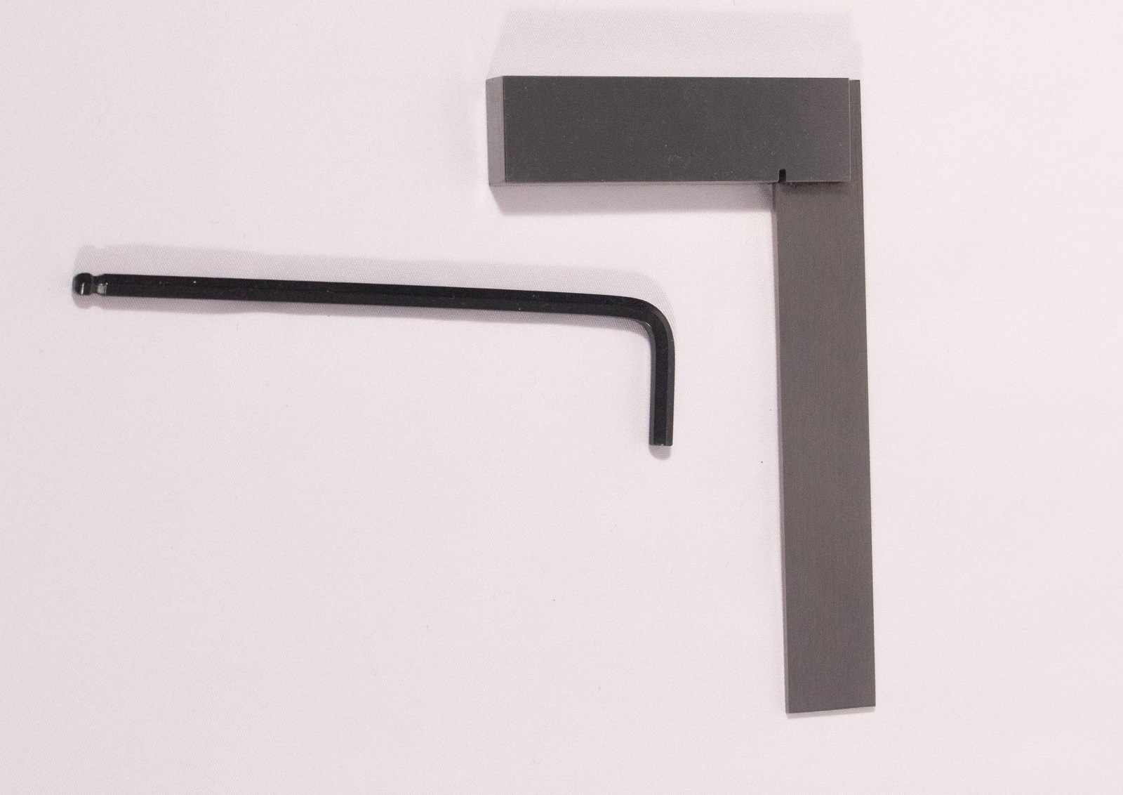
- call_split Hex Key for M5 bolts
- 3mm for the kit version
- 4mm for the BOM version
- Flat surface
- Small carpenter's square
warning It is critical that the frame be as square as possible and to aid in that process you need to find the flattest surface you have available. Do not just assume something is flat! Check with a straight-edge or ruler by placing the edge against a surface and shining a light behind it to see if you can see any major gaps. Less than 1mm gap anywhere is critical and no visible gaps is preferred. A stone countertop is often a great flat surface if you have one but most desks or tables will probably work. Just check first!
That being said, we don't mean to make you fret over this step for hours. Get it as close as you reasonably can to square.
Frame Sides
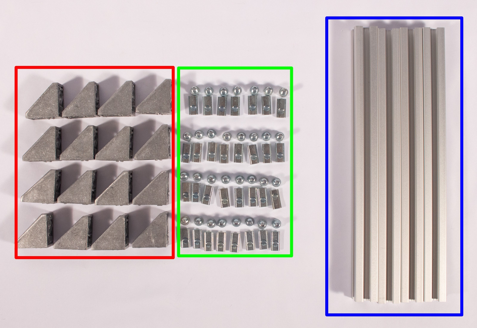
Components
Click on the images to make them bigger! :)
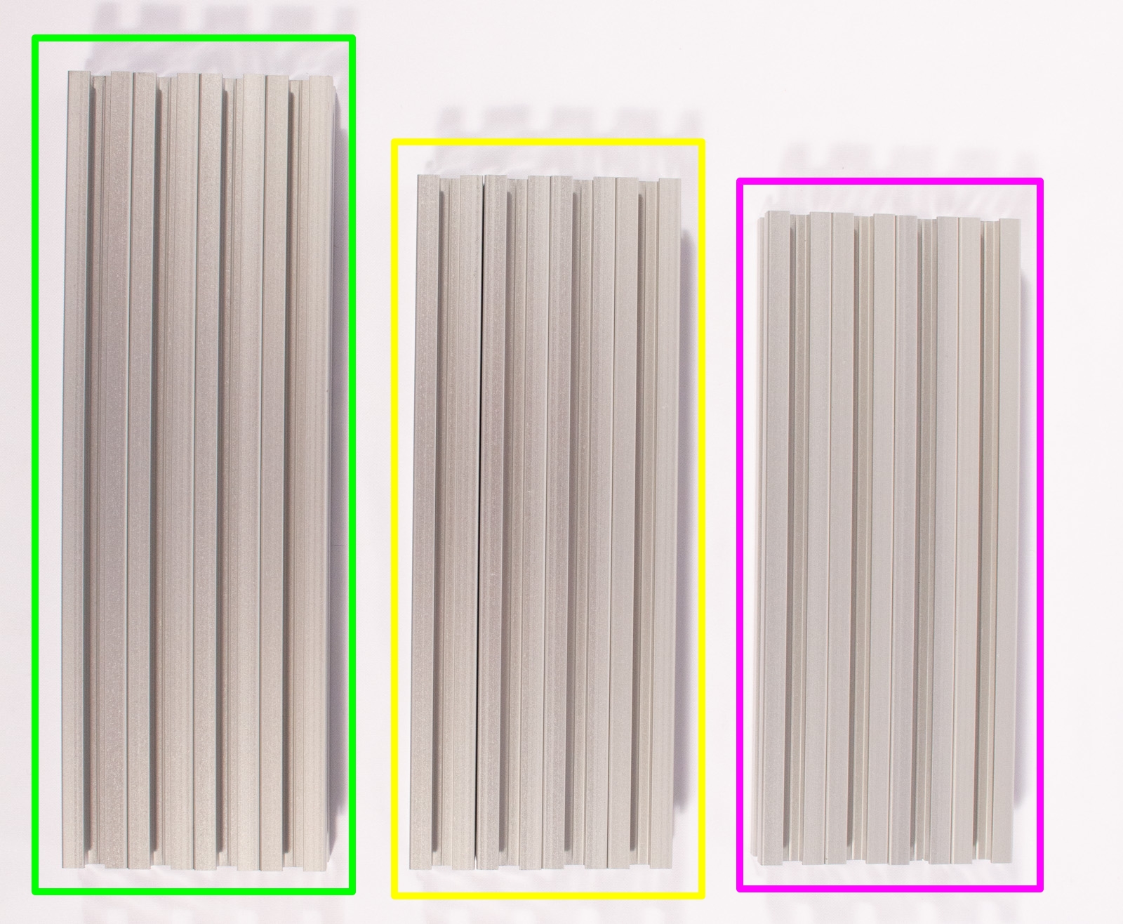
- 240mm Aluminum Extrusion, HFS5-2020-240 (x4)
- 210mm Aluminum Extrusion, HFS5-2020-210 (x4)
- 200mm Aluminum Extrusion, HFS5-2020-200 (x4)
- call_split Extrusion Corner Brackets. Misumi BOM components shown, Kit version visually similar.
- Kit Version
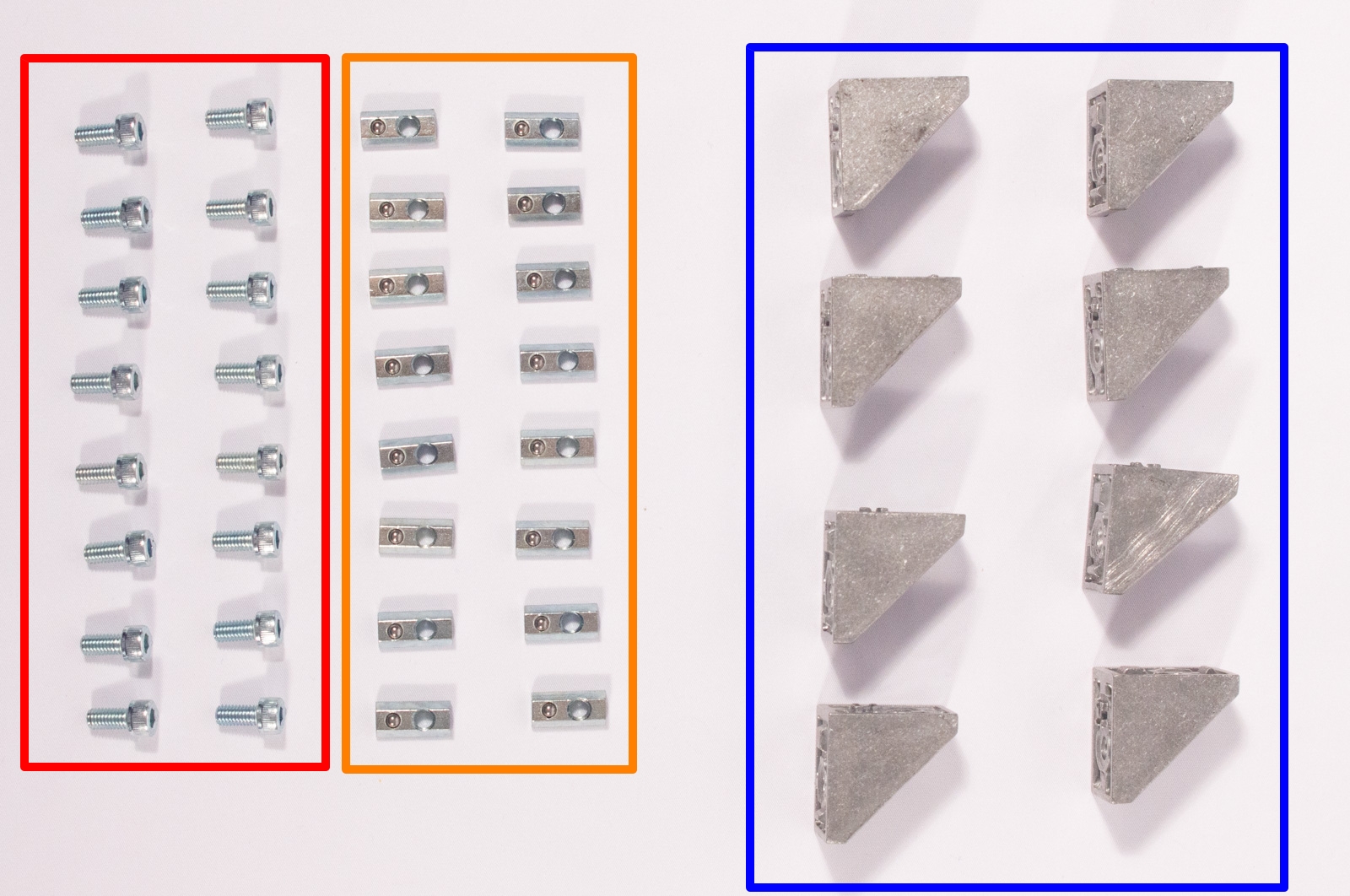
- 2020 Corner Brackets (x8)
- M5x8mm bolt (x16) (Black pan-head for kit)
- Post Assembly Spring Nut (x16)
- BOM Version (HBLFSN5-SEP)
- 2020 Corner Brackets, HBLFSN5 (x8)
- M5x10mm bolt, CB5-10 (x16)
- Post Assembly Spring Nut, HNTP5-5 (x16)
- Kit Version
call_split FOR THE BOM VERSION: The bolts and spring nuts that come with the HBLFSN5-SEP extrusion bracket sets are effectively the same M5x10mm bolt (CB5-10) and Post Assembly Spring Nut (HNTP5-5) used elsewhere in this kit, though the bolts may be black instead of chrome, for cost reasons. It's just cheaper to buy the brackets as a set with the bolts and nuts. Feel free to sort the bolts and nuts with the others.
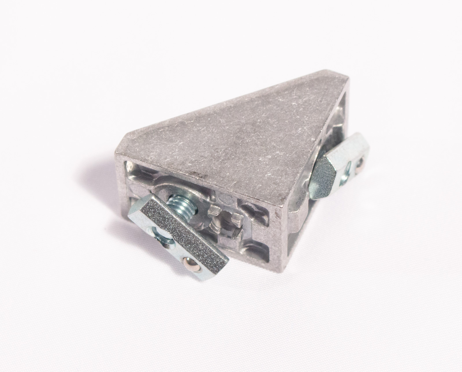
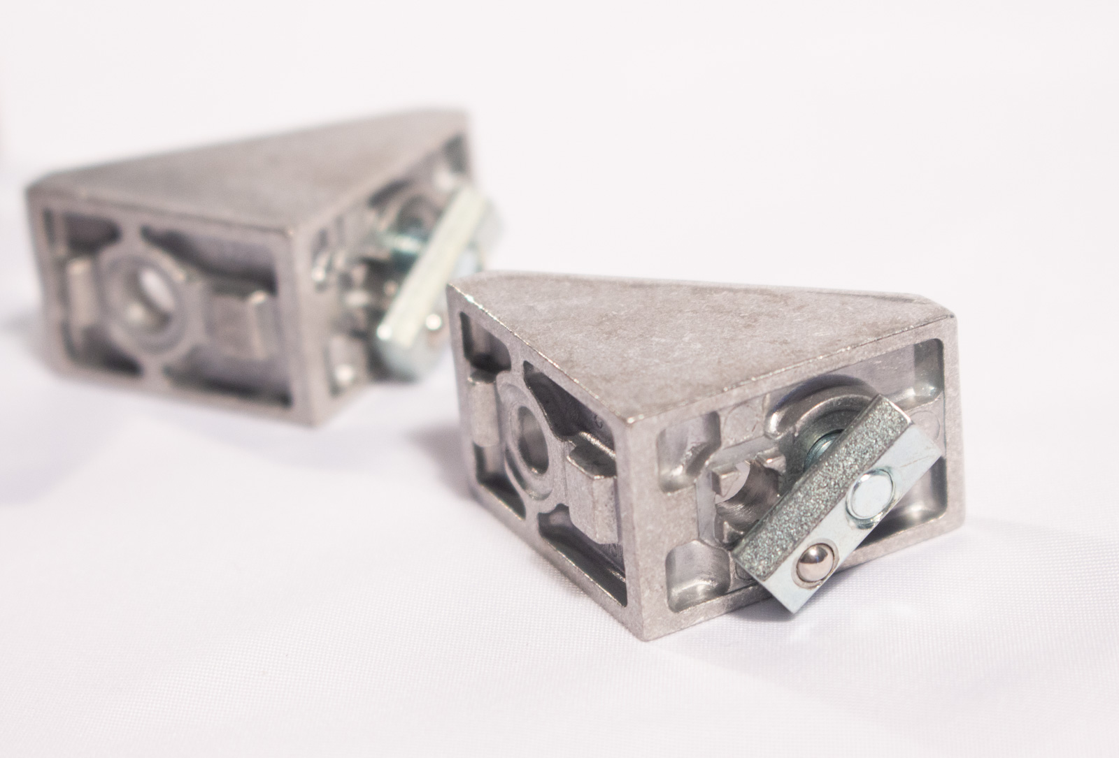
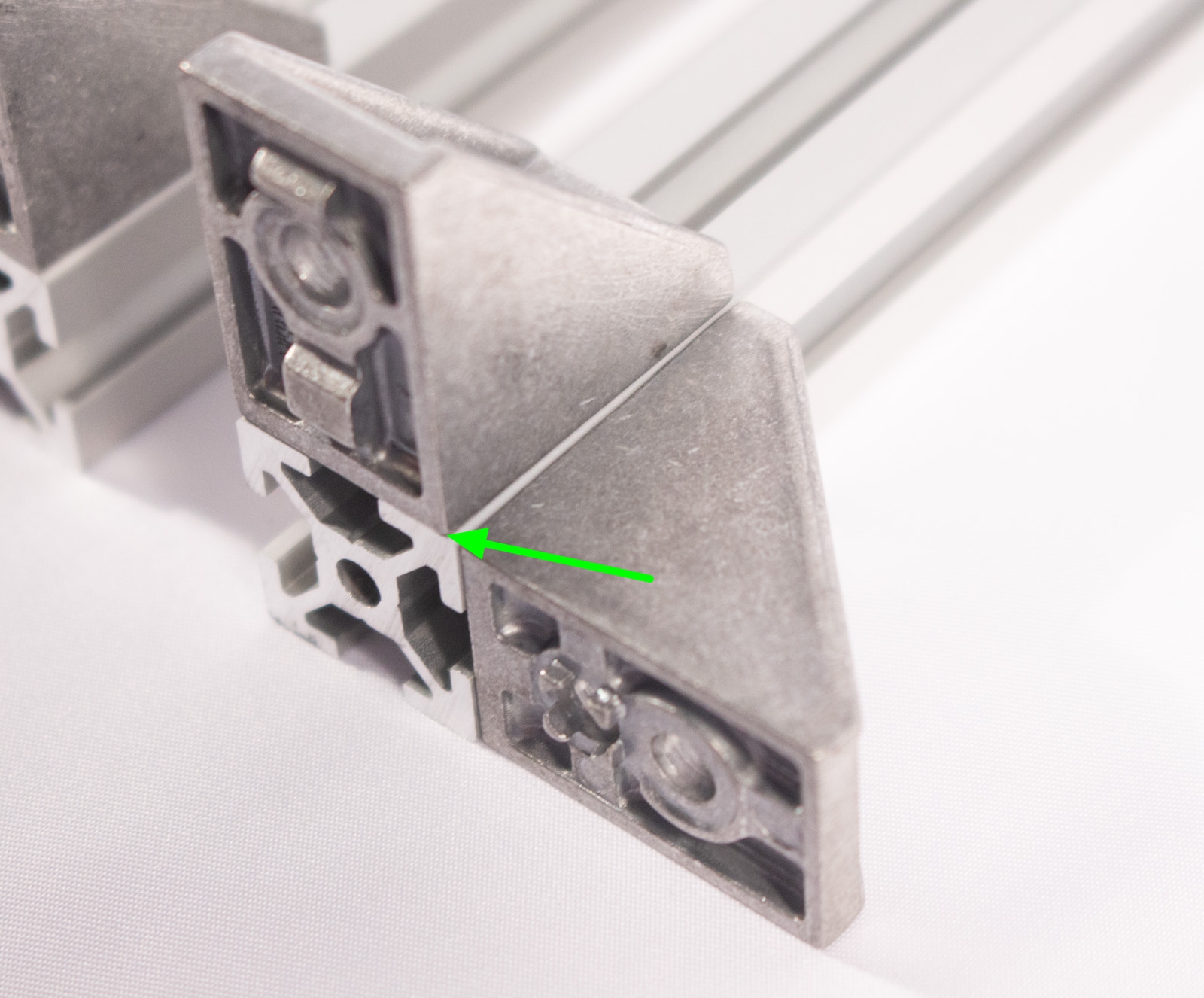
call_split FOR THE BOM VERSION: The corner extrusion brackets have 2 holes on one side, and one on the other. Aside from the fact that you should always use the outter hole on the side with 2 holes, it does not matter which way you orient the brackets, when assembling the frame. The kit version of these brackets only has one hole per side.
warning The post assembly spring nuts have a "ball detent" (a spring-loaded, captive, ball bearing) on one side. This ball must always face inward, towards the center of the extrusion, when inserting!
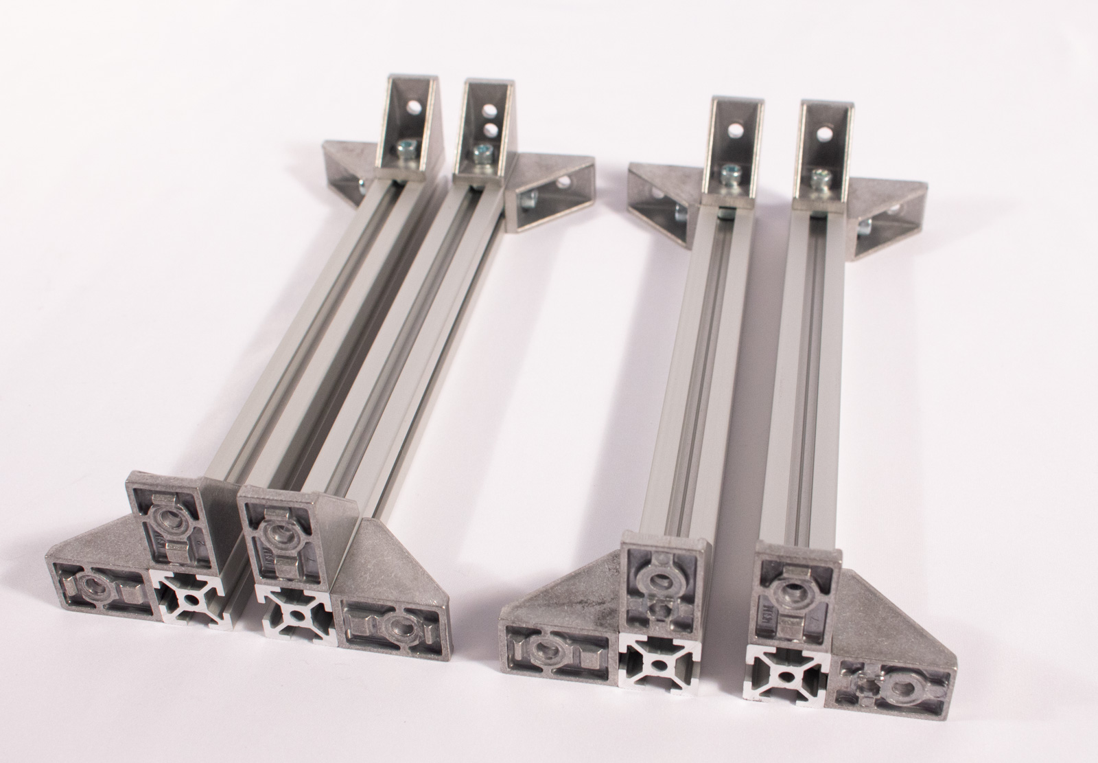
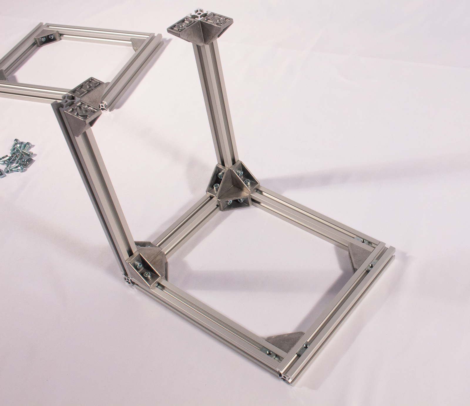
Assemble Frame Side


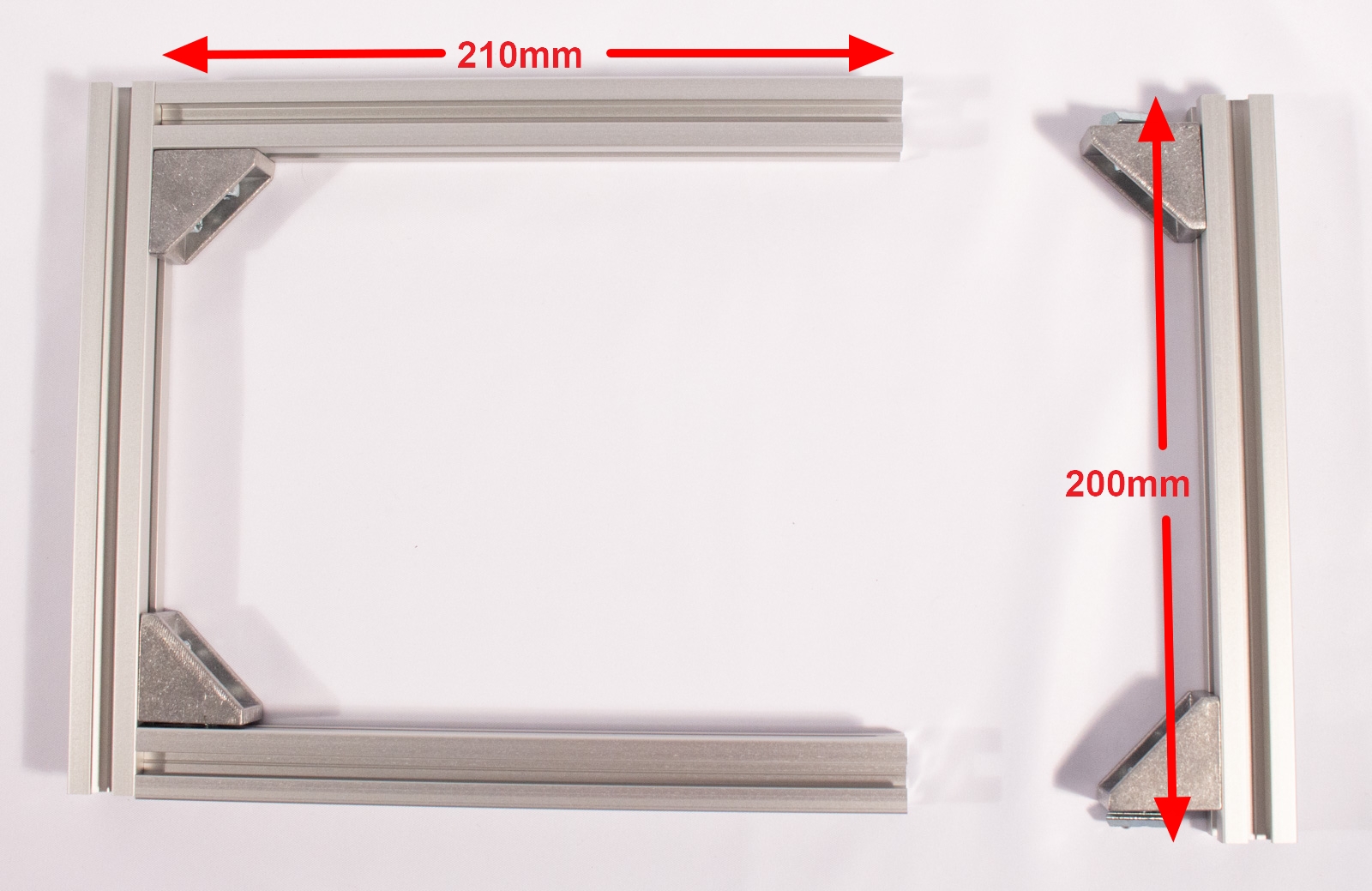
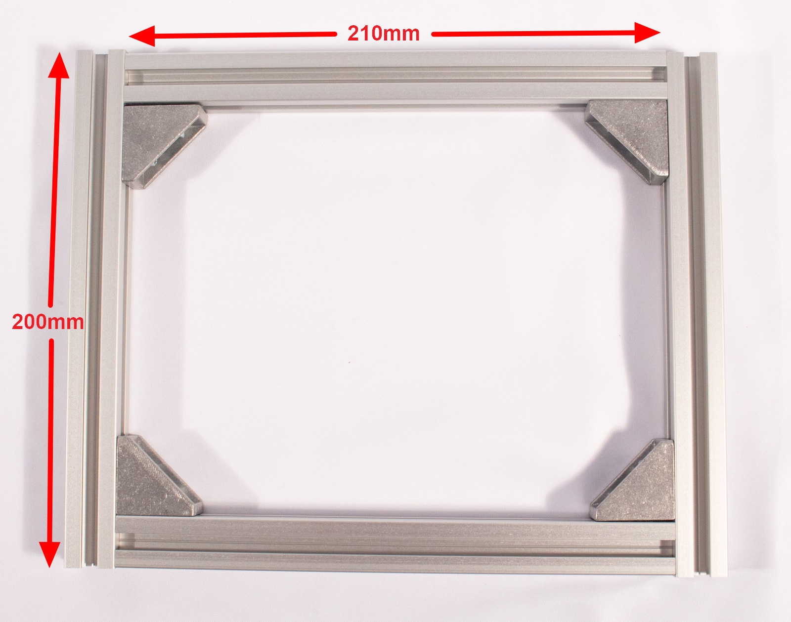
warning It is extremely important that the 200mm extrusions are the ones that will have exposed ends, when assembled. The 210mm extrusions should have their ends butted up against the 200mm extrusions, as shown in the pictures.
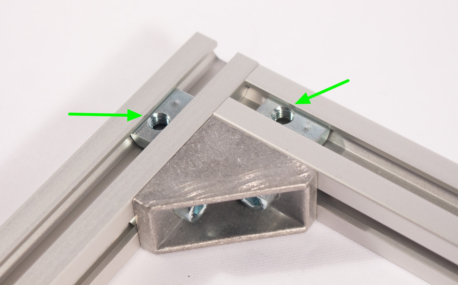
- Take 4 brackets and, for each, insert a bolt into each side, and then lightly twist on a spring nut. For the side with two holes, use the hole farthest from the corner.
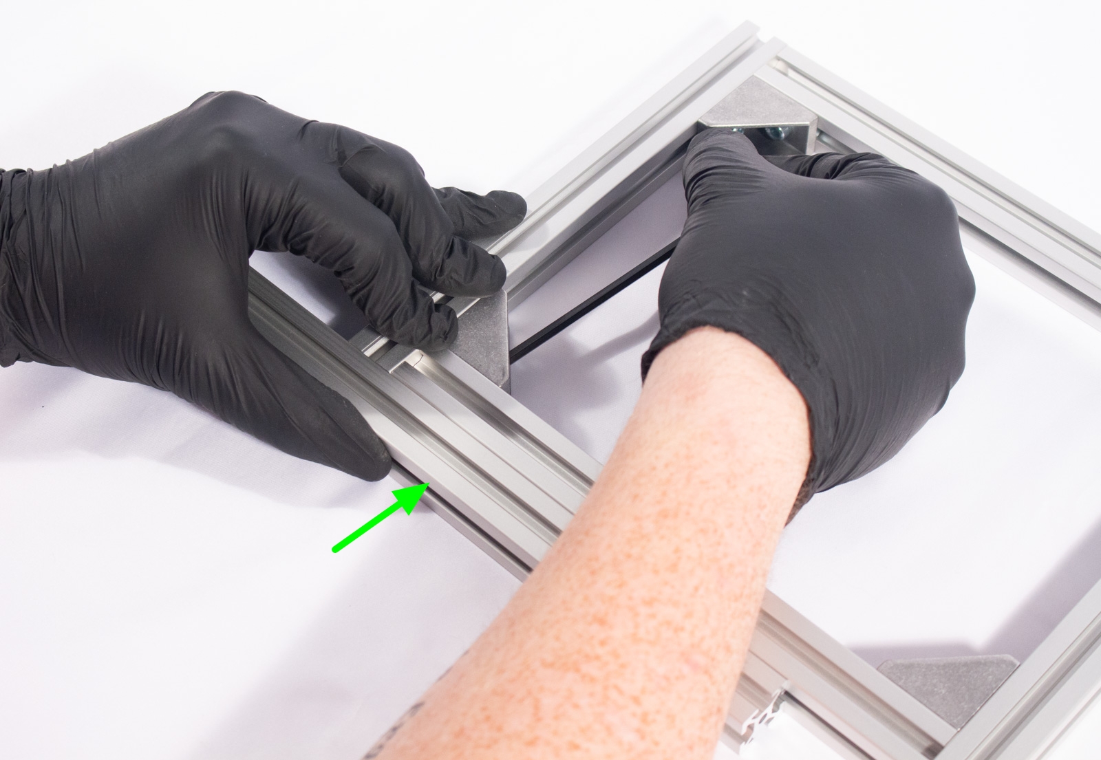
- Lay 2 of the shortest, 200mm extrusions beside each other, on your chosen flat surface, and from each end, slide a bracket/bolt/nut assembly into the channel, as shown.
- Now, take 2 of the 210mm extrusions, and slide them onto the bracket nuts of one 200mm extrusion, and then the other. As shown, the edge of the 210mm extrusions should be flush with the ends of the 200mm extrusions.
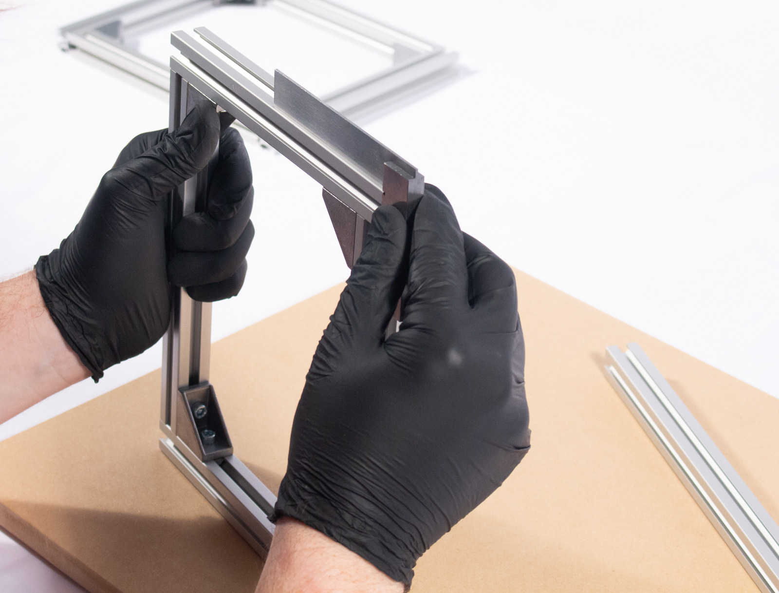
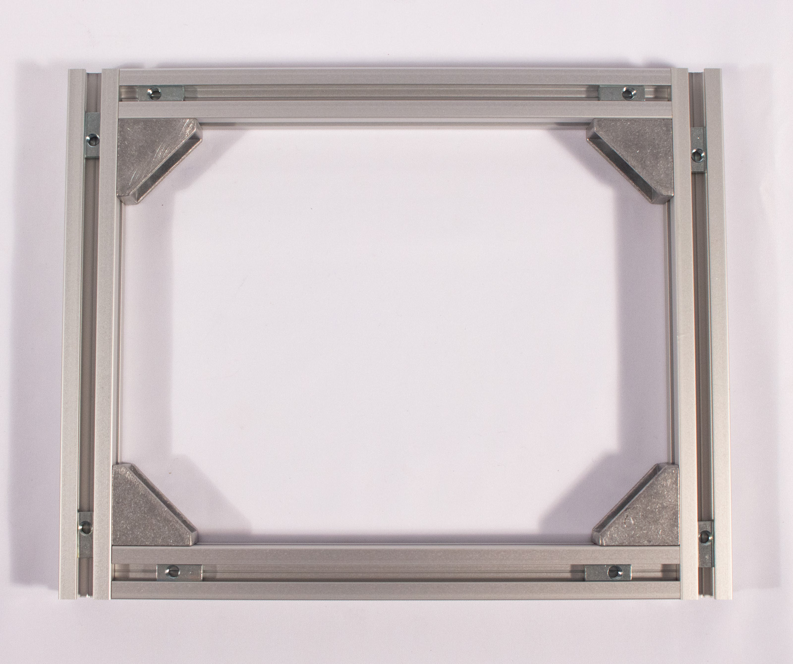
- Using the hex key, start to tighten the bolts to barely finger tight, using the longer end of the hex key. Tighten opposing corners, and then the remaining 2 corners, as shown in the diagram.
- Once the bolts are tight enough, to roughly hold the frame to shape, press the whole assembly flat against your work surface, and check each corner with a square. If needed, make any adjustments, so the whole side frame is as square and flat as possible.
- Once you are satisfied, tighten all bolts, with the short end of the hex key (for more torque). Use the same opposing corner pattern used above.
Repeat
Do everything from the previous step, again, with the remaining 200mm and 210mm extrusions.
Complete the Frame
Components
- 240mm Aluminum Extrusion, HFS5-2020-240 (x4)
- call_split Extrusion Corner Brackets. Misumi BOM components shown, Kit version visually similar.
- Kit Version
- 2020 Corner Brackets (x8)
- M5x8mm bolt (x16) (Black pan-head for kit)
- Post Assembly Spring Nut (x16)
- BOM Version (HBLFSN5-SEP)
- 2020 Corner Brackets, HBLFSN5 (x8)
- M5x10mm bolt, CB5-10 (x16)
- Post Assembly Spring Nut, HNTP5-5 (x16)
- Kit Version
Assemble Horizontal Extrusions

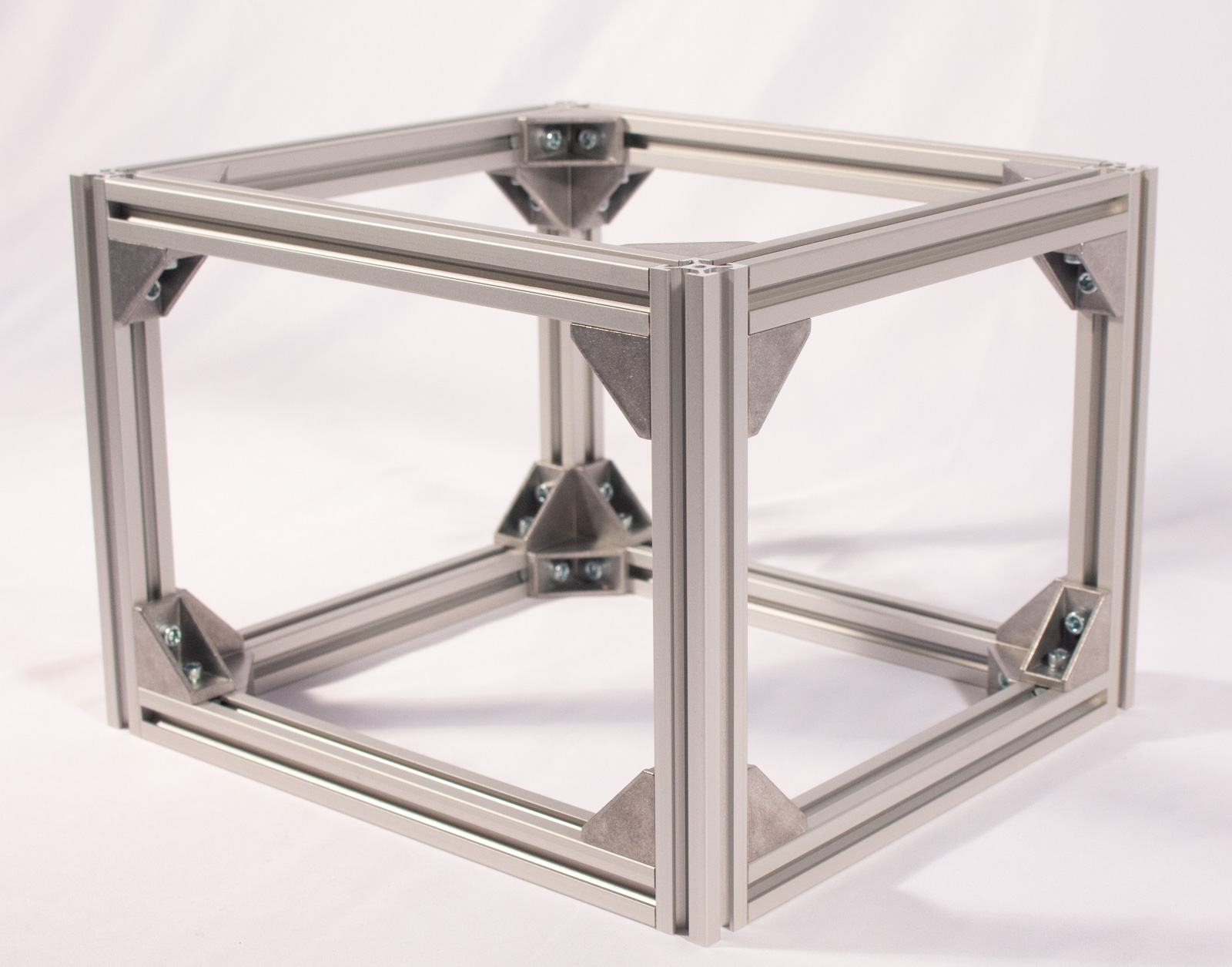
- Take the remaining 16 extrusion brackets, insert a single bolt, and then twist on a spring nut to each.
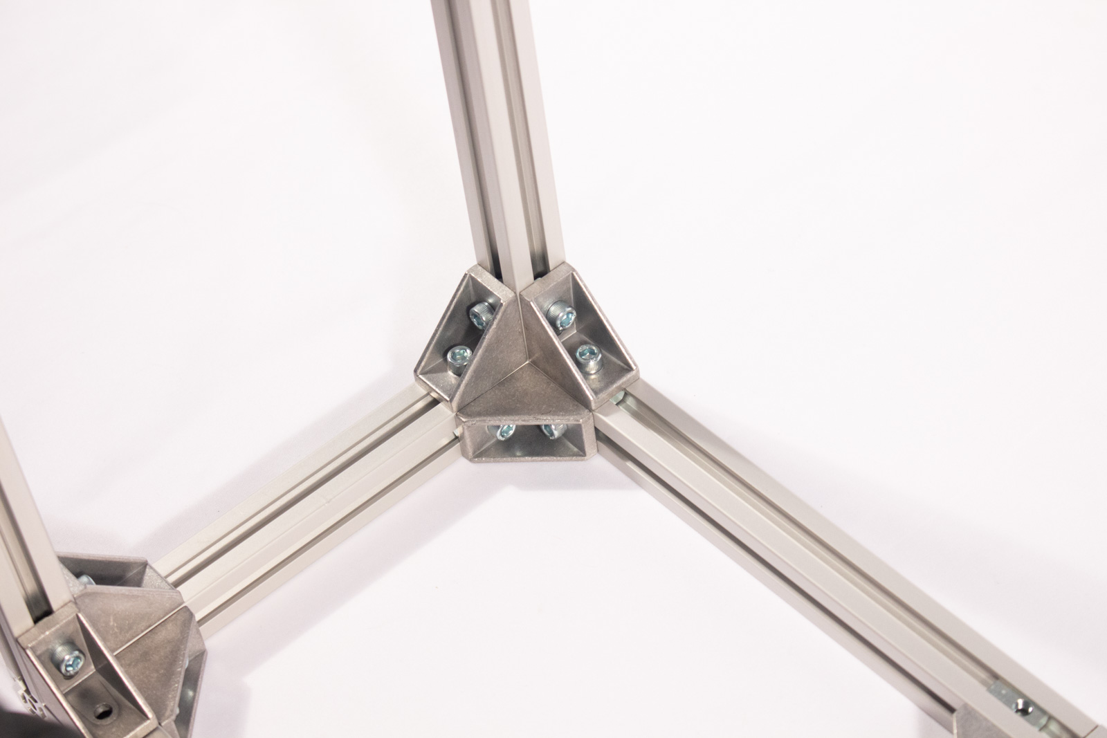
- On each of the 240mm extrusions, slide 2 brackets onto each side, as shown. They should be 90° opposed to each other, with the same orientation on both sides.
- Make sure each bracket is flush with the end of the extrusion, and tighten the bolt, so that they won't move easily, but not all the way.
- On each side frame assembly, insert 2 spring nuts, in each corner, as shown.
- Starting with one side frame assembly, match up a 240mm extrusion to each corner, and insert the remaining bolts into each of the brackets, mating up with the spring nuts, and tightening lightly.
- Repeat the process with the other side frame assembly.
Squareness Check and Tightening
- Start by resting the frame on any of the sides with the 240mm extrusions, and making sure that it can be pressed flat, against your work surface, without any wobble. Also check that all of that side's corners are square. Tighten all bolts on that side.
- Flip the frame 180° and repeat the above process.
- Flip the frame 90° check for flatness, and square, again. Tighten all bolts.
- Flip to the remaining 240mm side, check for flatness, and square. Tighten all bolts.
- Now check all 6 sides, against your work surface, and ensure that there's no wobble.
- Check all 3 sides, of all 8 corners, with a square.
- If any side wobbles, loosen the bolts on one corner at a time, press down and re-tighten to see if the wobble goes away.
- Visually inspect the end of each extrusion (where it was cut), and make sure that the mating extrusion sides are completely flush with the end.
- When satisfied, double-check the tightness on all bolts. With a ~100mm long hex key, they should be as tight as you can get them, with one hand, using the long side for leverage.
W00T! That's one nice looking aluminum cube! Head on to the X-Axis steps.