X-Axis Assembly
Tools Required
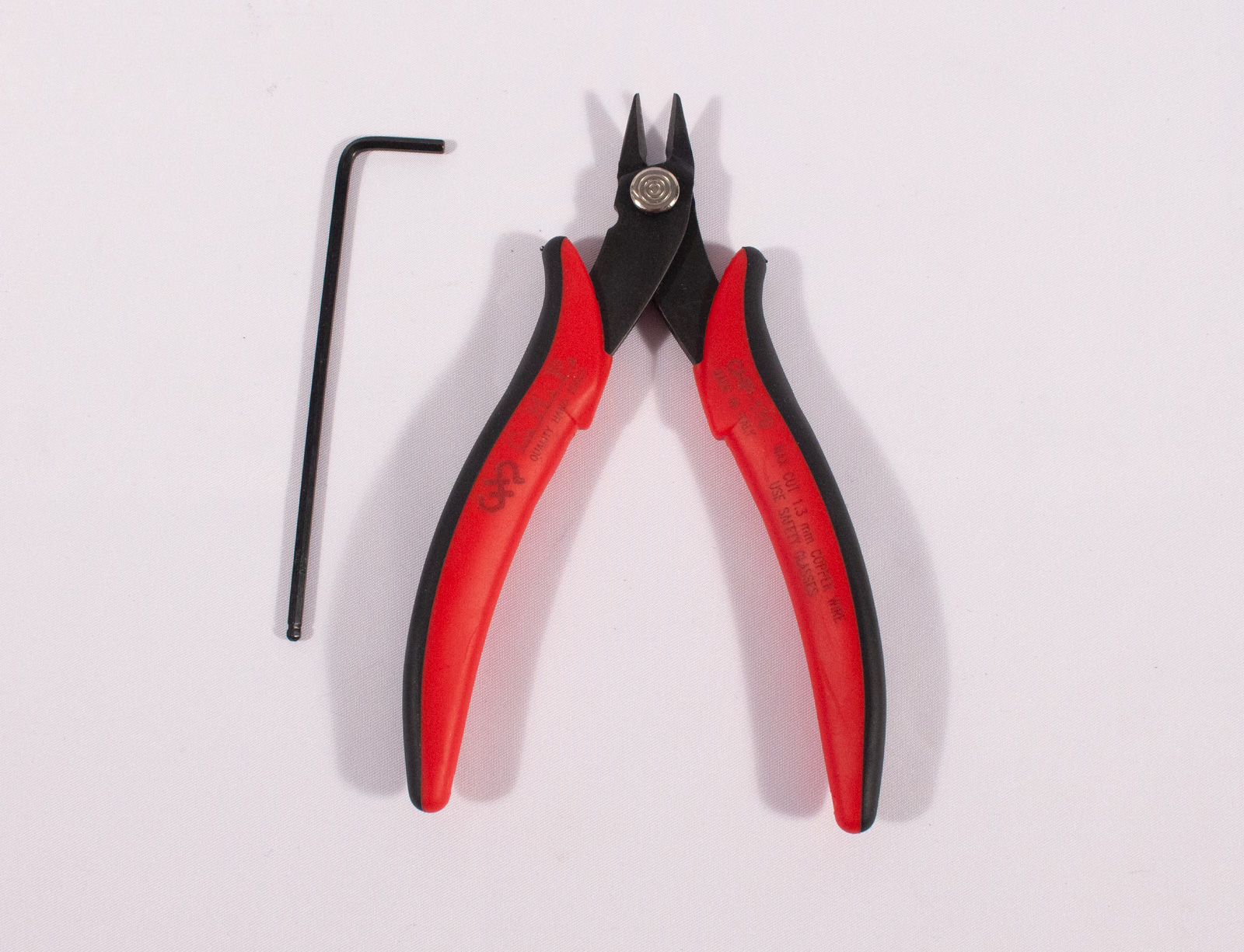
- 2.5mm Hex Key for M3 bolts
- Snippers for cutting belt
Y Drive Side
Components
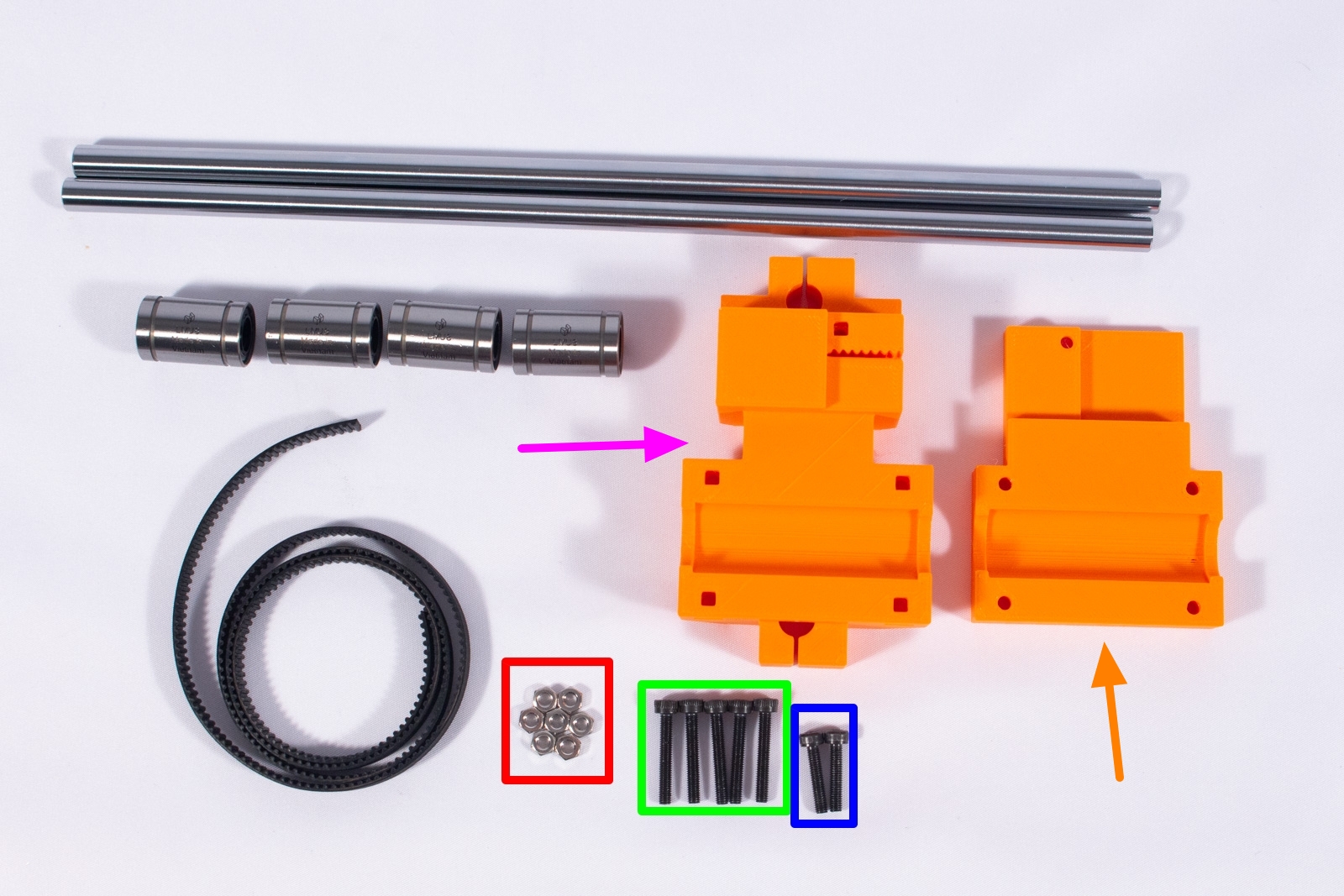
Yes, some of the components listed here have Y in their name. The X-Axis is mostly held together with some components from the Y-Axis
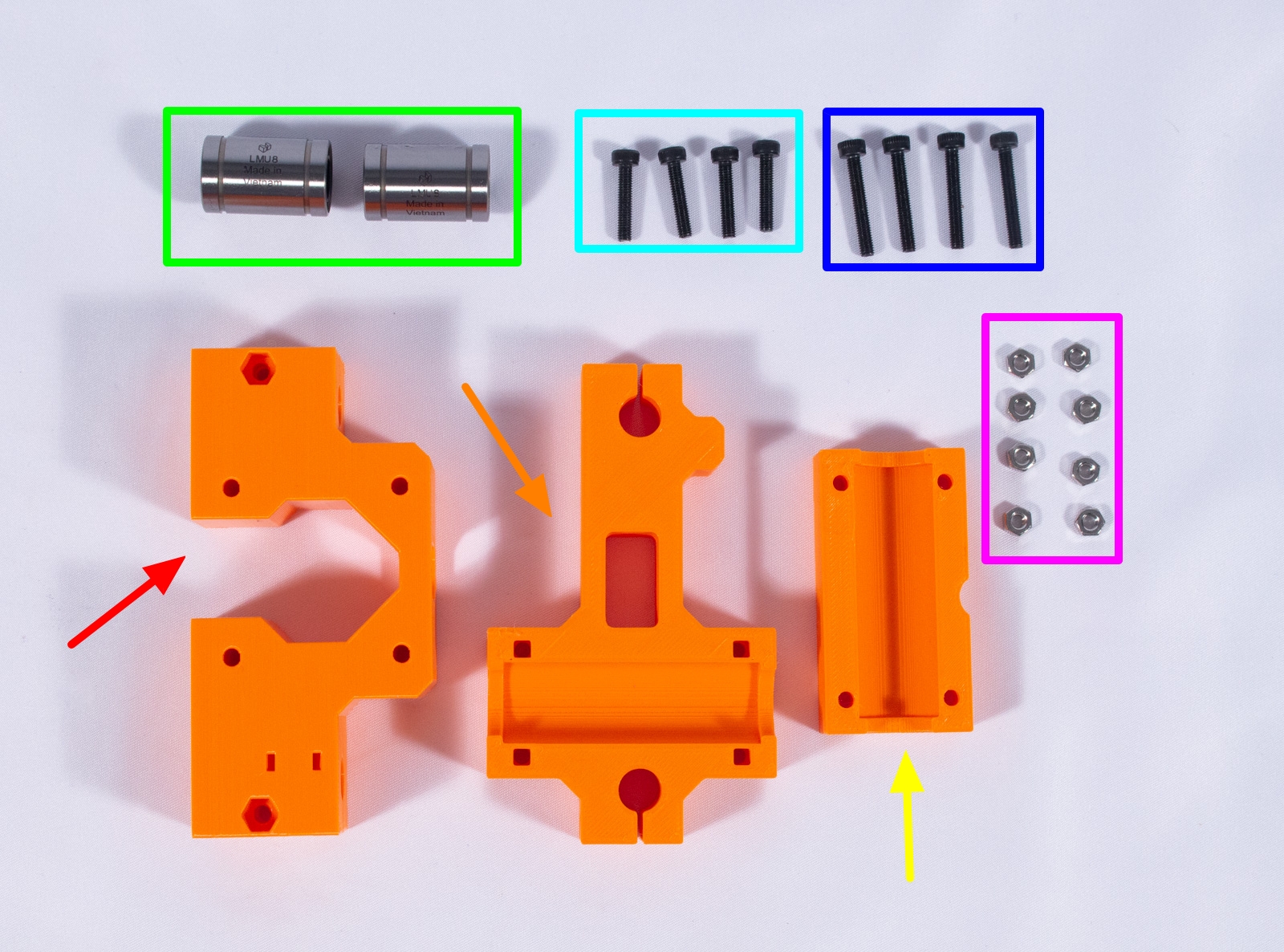
- LMU8 Linear Bearing (x4)
- 250mm x 8mm Linear Rod, PSFJ8-250 (x2)
- Y_Drive_Main (x1)
- Y_Drive_Plate (x1)
- GT2 Belt 550mm
- M3 nut (x7)
- M3x14mm bolt (x2)
- M3x20mm bolt (x5)
Assembly
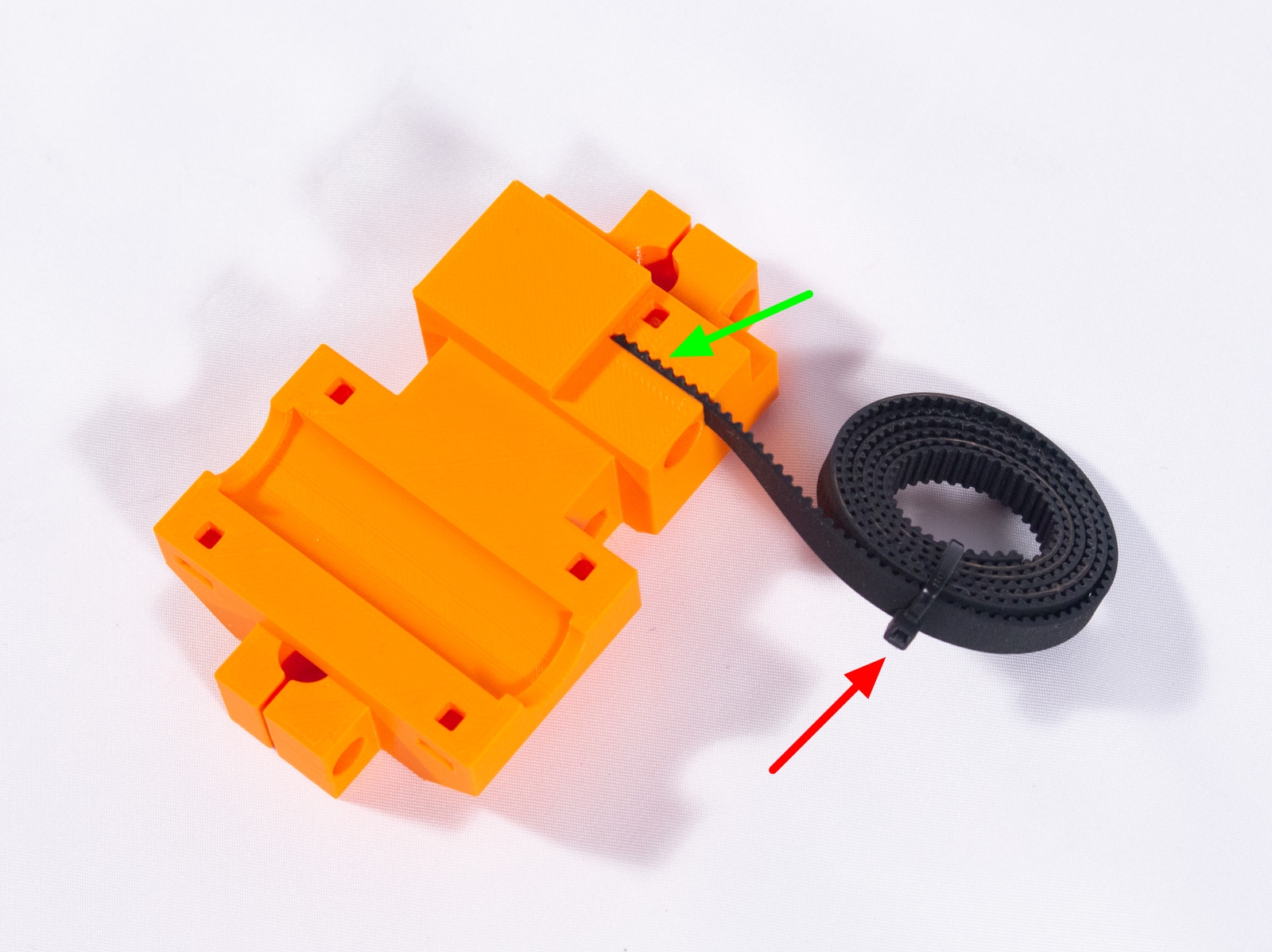
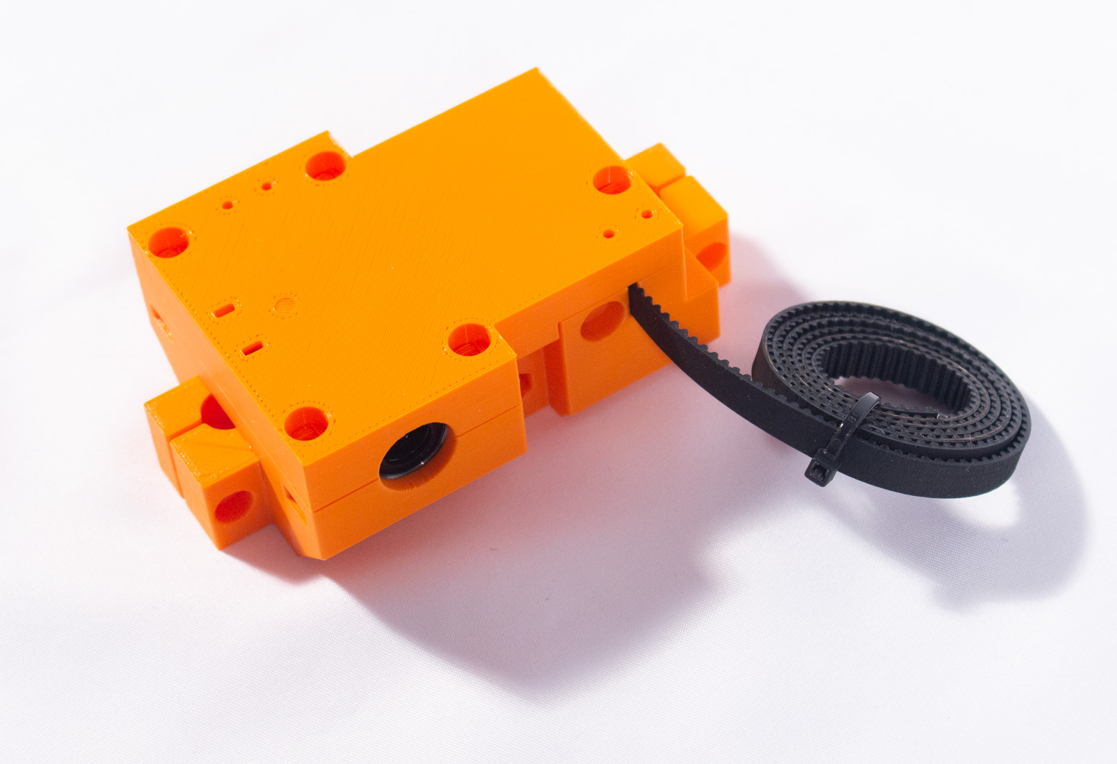
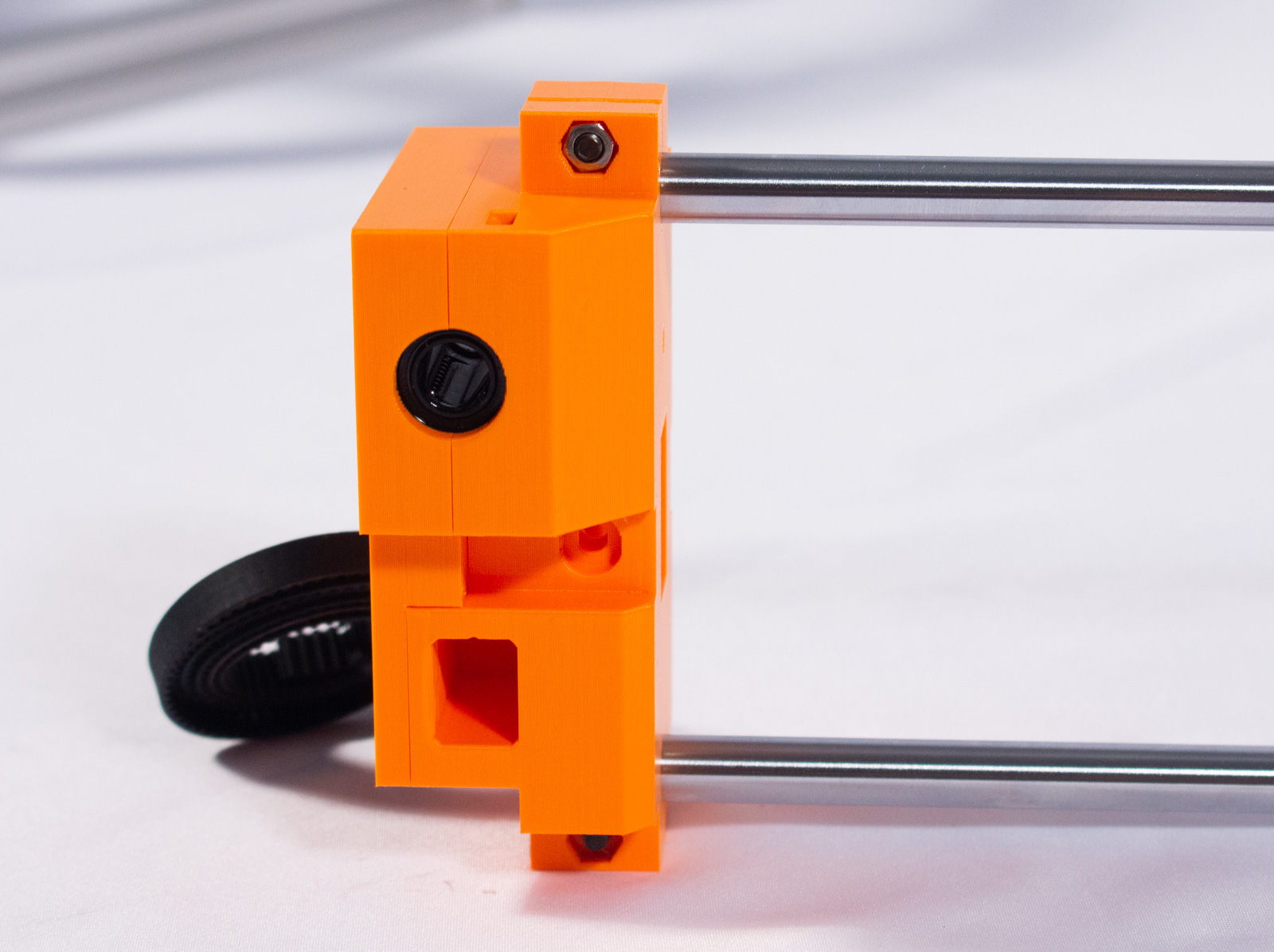
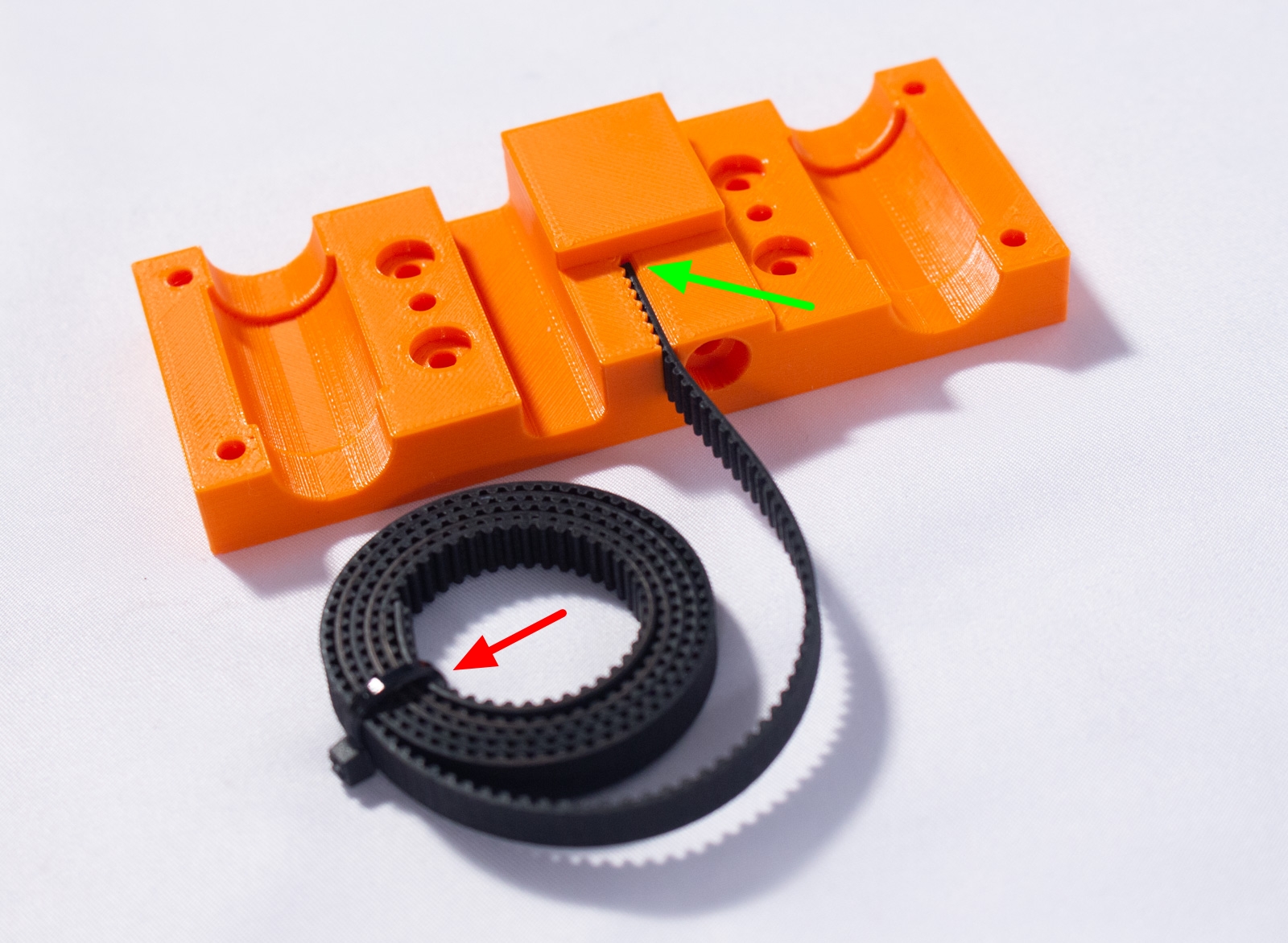
- Insert one end of the GT2 belt into the belt holder in Y_Drive_Main as shown, ensuring it is fully inserted flush. We recommend rolling up the belt at this point and securing it with a zip tie or rubber band. We'll get back to it later.
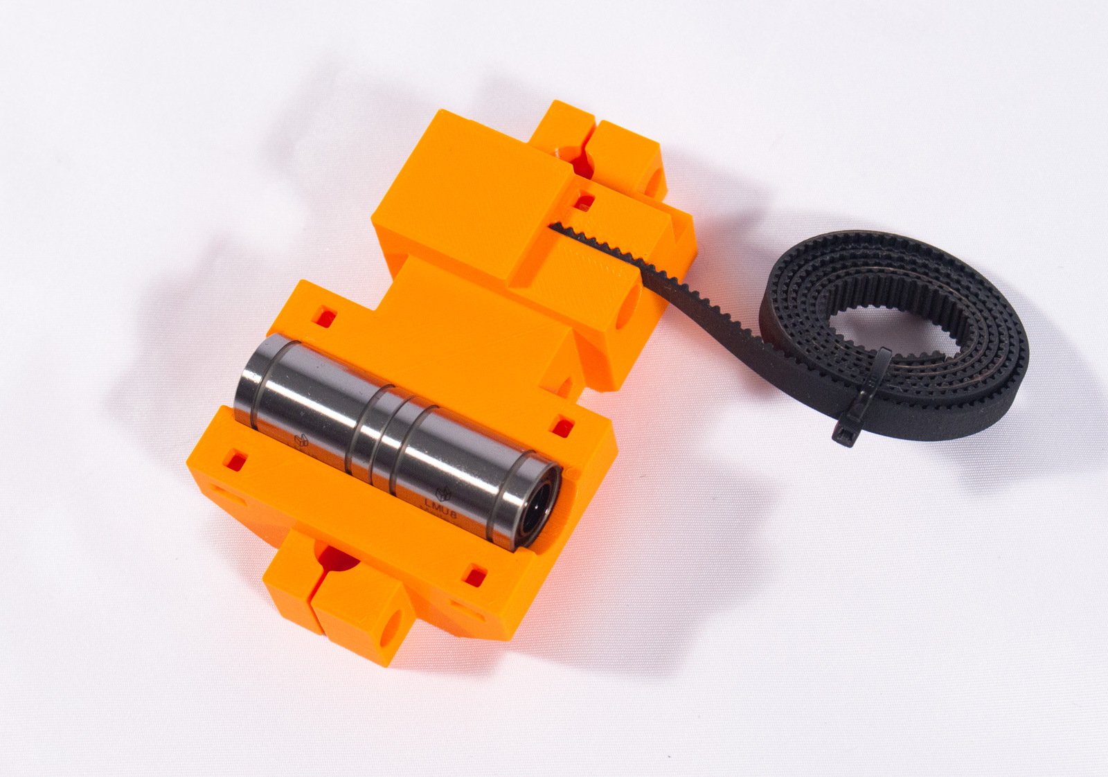
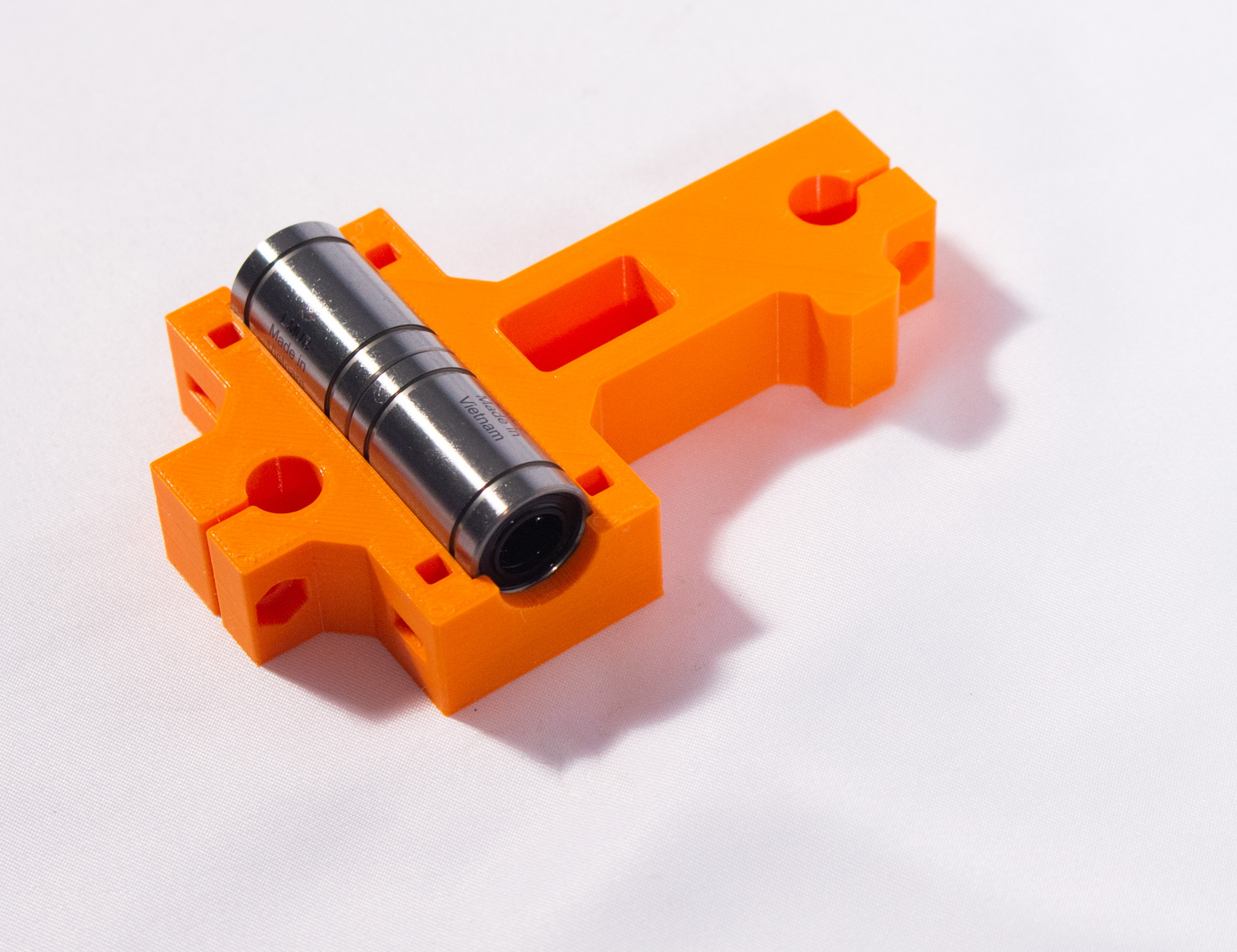
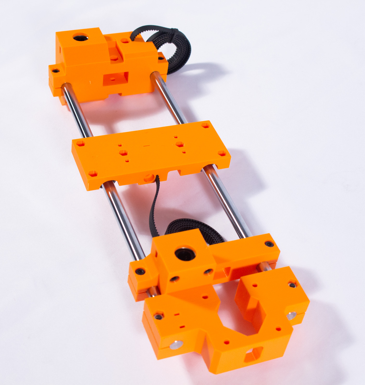
- Insert 2 of the LMU8 bearings into the recess of Y_Drive_Main then cover with Y_Drive_Plate as shown.
warning If the bearings do not drop in with little force, DO NOT force them! This may cause them to go in out of alignment. Instead, place both bearings onto one of the 8mm steel rods directly next to each other. Use the steel rod to help push them into the bearing recess, which will keep them in the correct alignment. If you still cannot get the bearings into the recess please checkout the printing guide and make sure you followed those directions carefully. You may need to reprint.
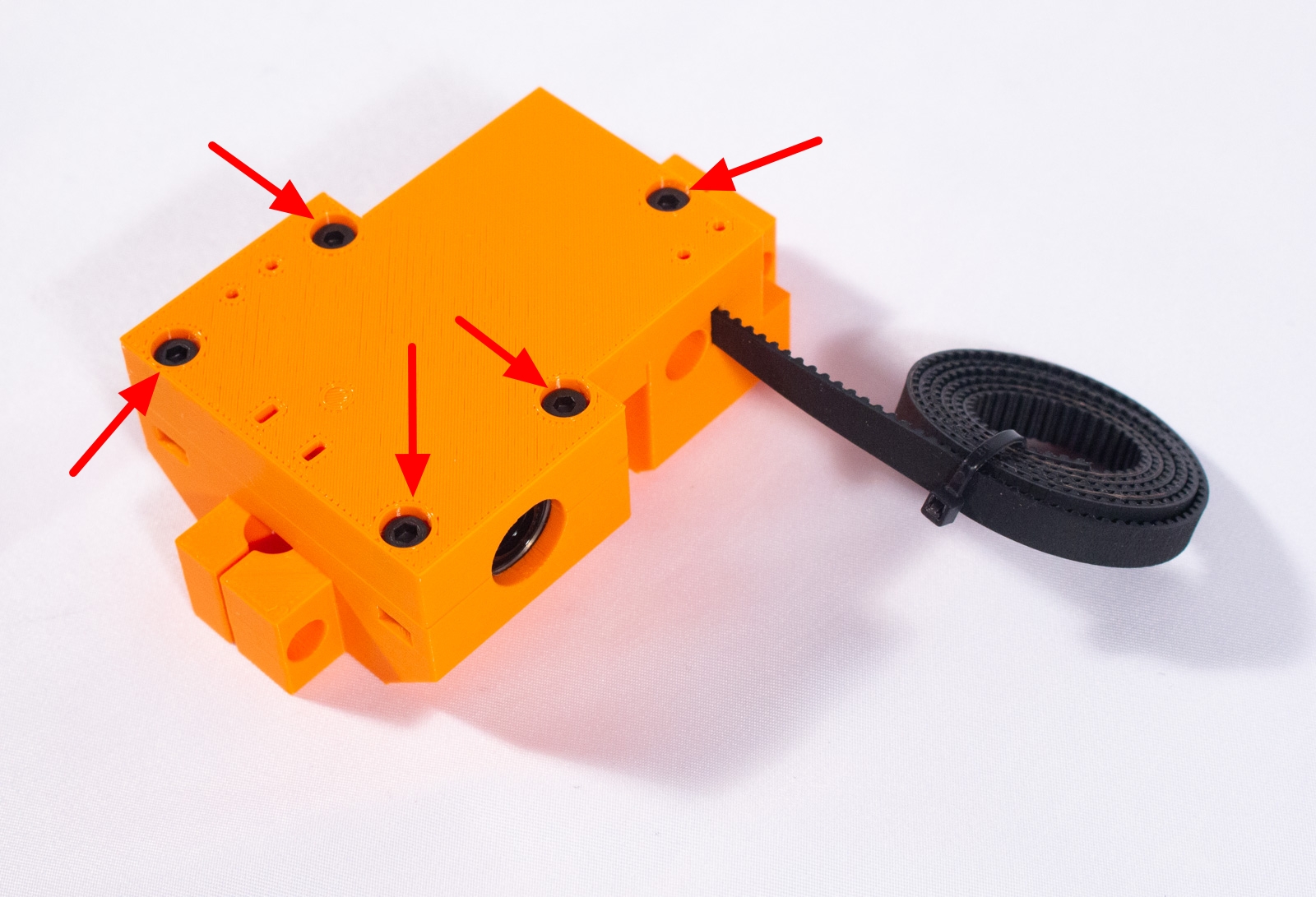
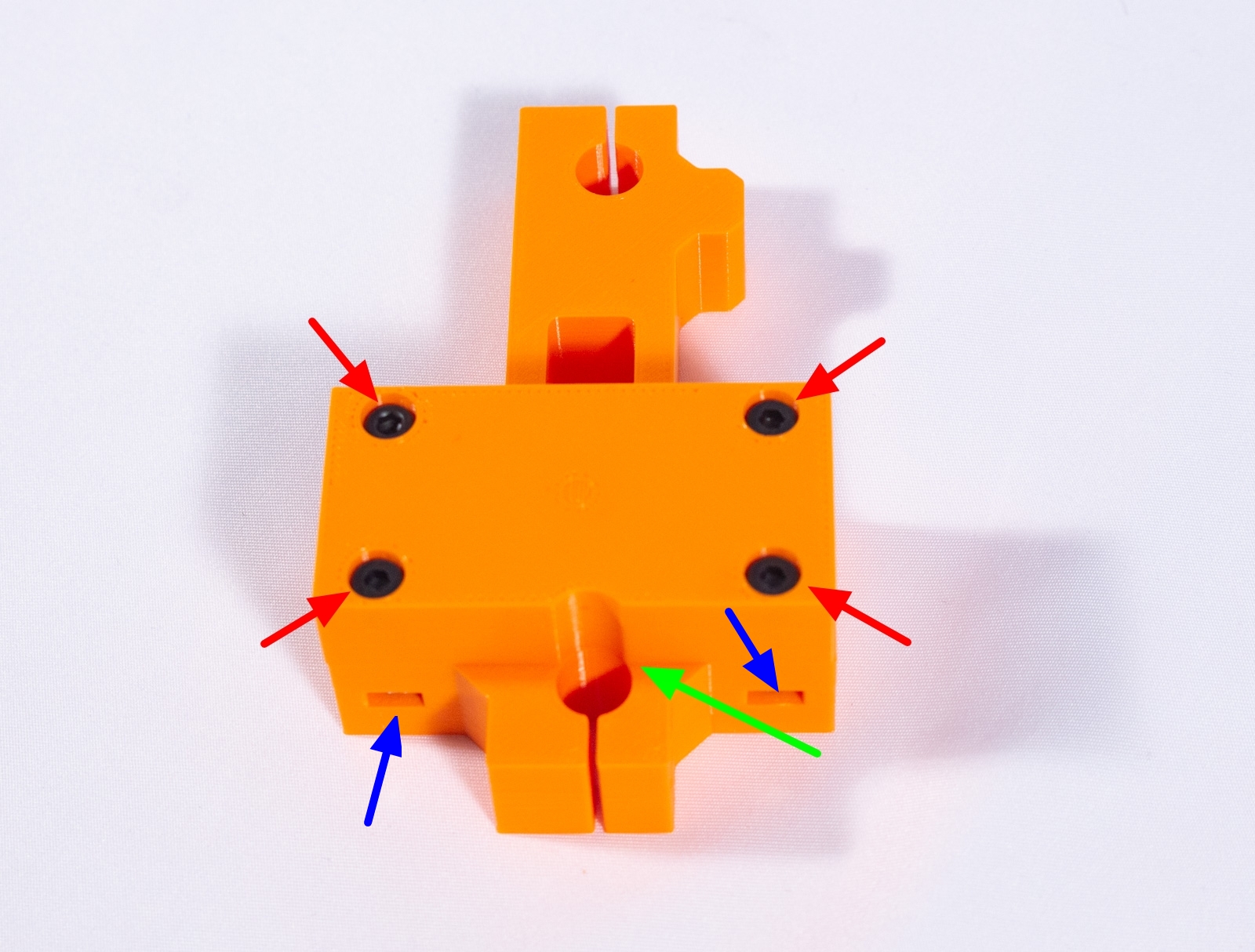
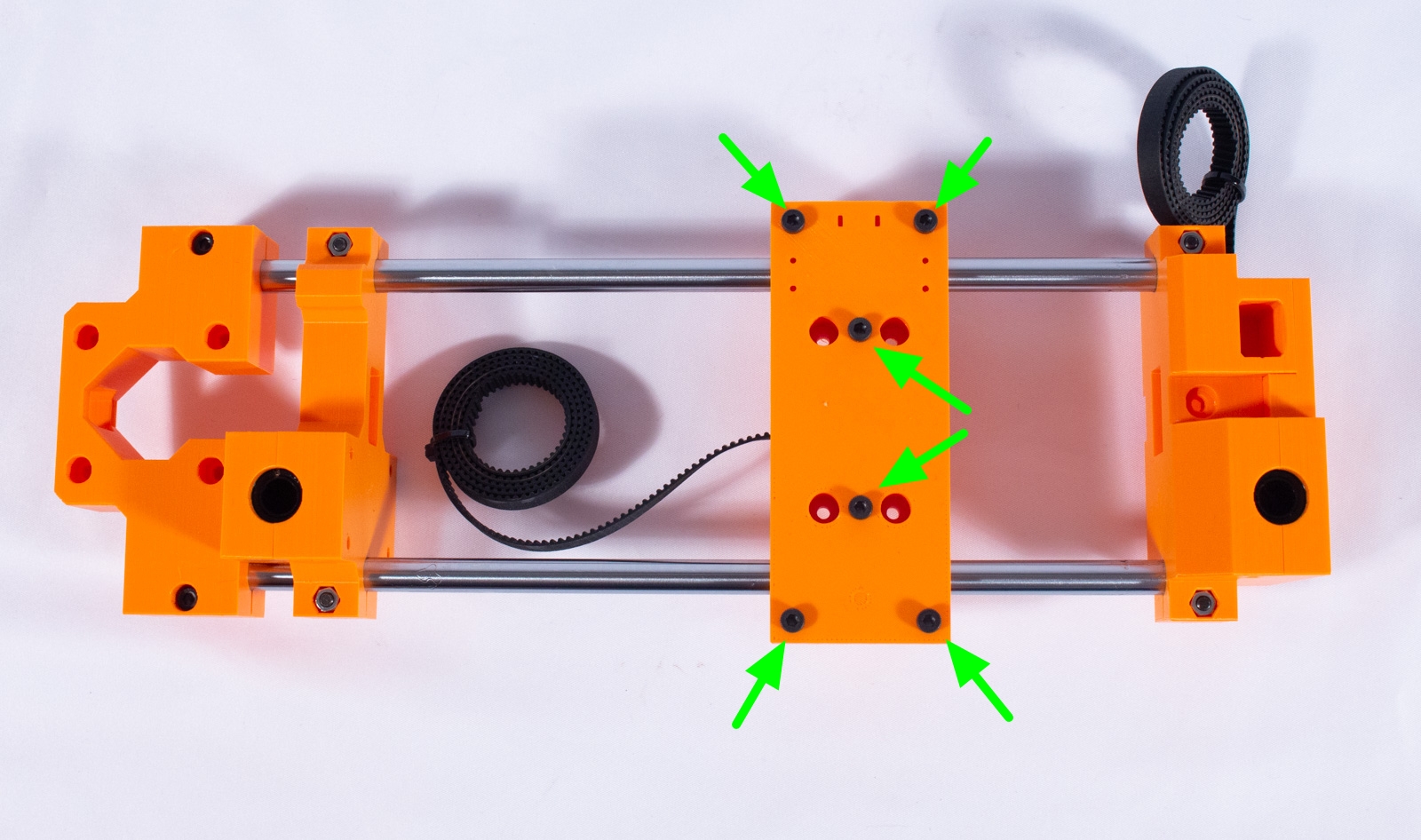
- Insert an M3 nut into each of the 5 recesses and then an M3x20mm bolt into the hole and tighten.
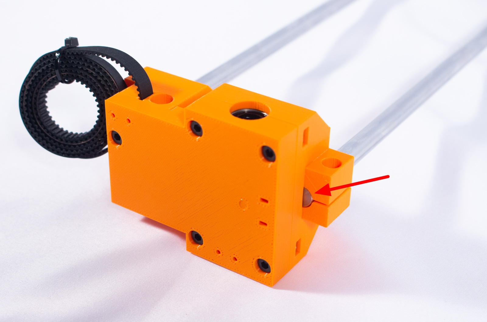
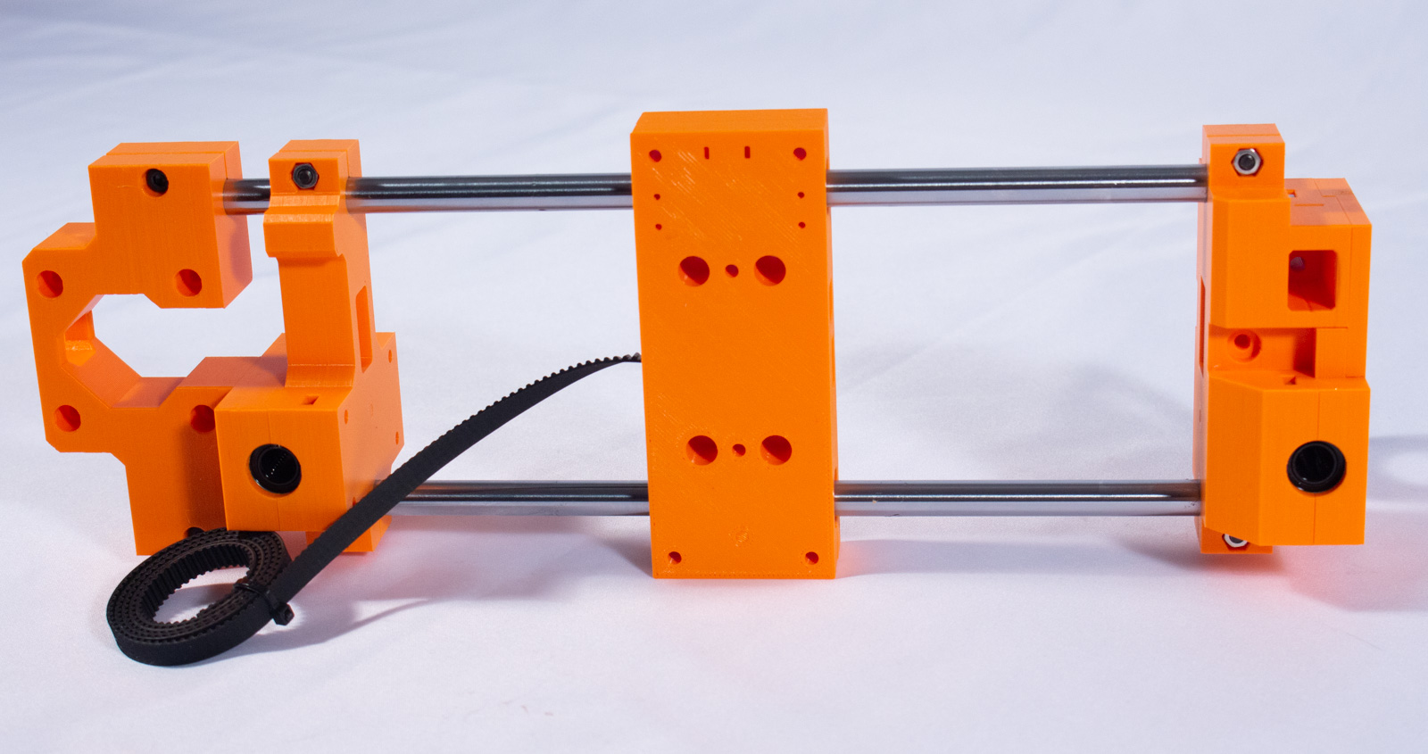
- Insert each of the 250mm rods into Y_Drive_Main as shown. Ensure that the ends of the rods are flush with the outside edge of the printed part.
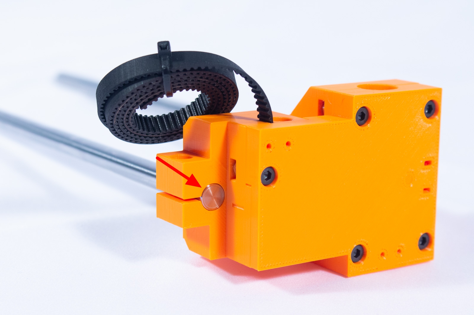
- Insert an M3x14mm bolt into each of the rod compression clamps and a nut on the opposite side (it has a hexagonal recess on the side for the nut).
- Tighten the bolts to lock the rods in place using the short side of the hex key for leverage. Do not overtighten these bolts.
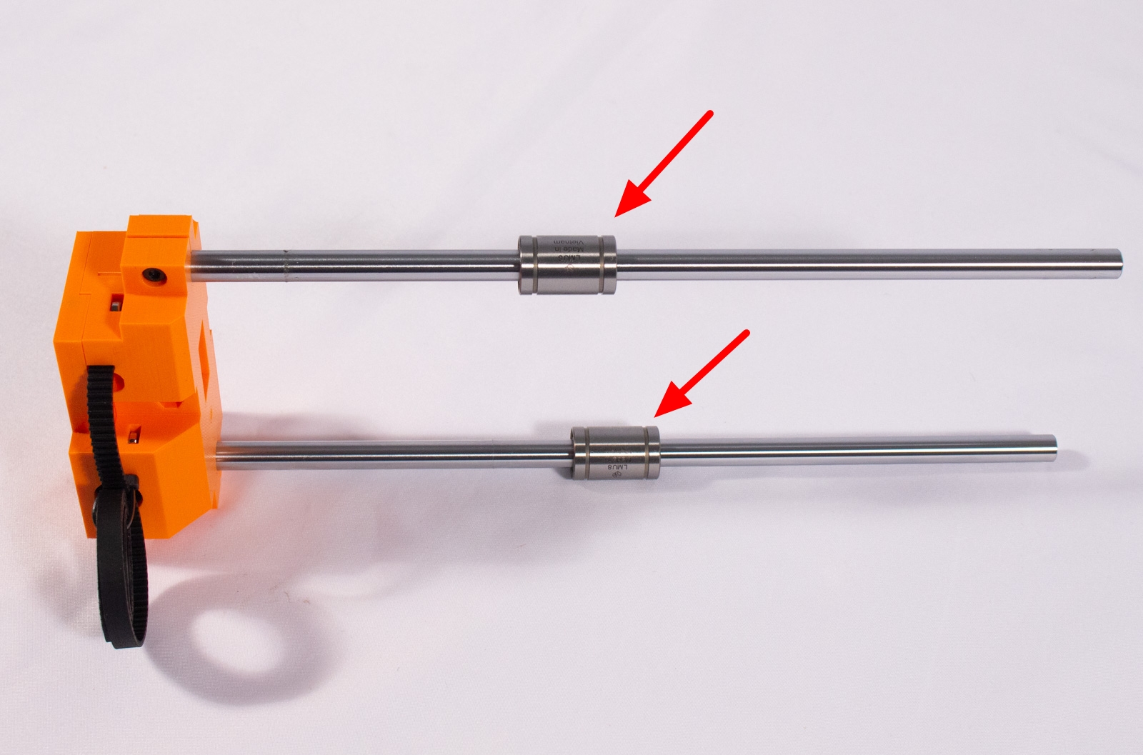
- Slide 1 of the LMU8 bearings onto each of the rods. Be careful when you do this that none of the balls are pushed out. The bearings should go on smoothly. If they are not you probably don't have it lined up properly.
Idle Side and X Motor Mount
Components
- LMU8 Linear Bearing (x2)
- Y_Idle_Main (x1)
- Y_Idle_Plate (x1)
- X_Motor_Mount (x1)
- M3 nut (x8)
- M3x20mm bolt (x4)
- M3x14mm bolt (x4)
Assembly


- Insert 2 of the LMU8 bearings into the recess of Y_Idle_Main then cover with Y_Idle_Plate as shown, ensuring the notch is at the bottom lining up with the rod hole.
- Insert an M3 nut into each of the 4 recesses and then an M3x20mm bolt into each hole and tighten.
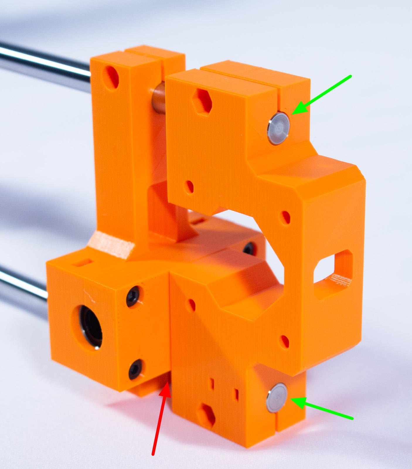
- Take the Y-Idle assembly and slide it over the ends of the 250mm rods as shown, leaving about 25mm of the rod protruding. DO NOT add the bolts and tighten this assembly yet!
- Slide X_Motor_Mount onto the ends of the rods making sure that the longer leg is on the bottom and that the ends of the rods are flush with the outside edge of the mount, as shown.
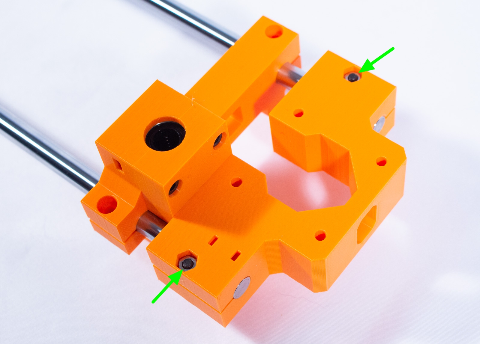
- Insert an M3x14mm bolt and M3 nut into each of the compression clamps and tighten using the short side of the hex key for leverage. Do not overtighten these bolts.
- Now move the Y-Idle assembly, if necessary, to ensure it is fully pressed up against the X_Motor_Mount. Insert an M3x14mm bolt and M3 nut into each of the compression clamps and tighten using the short side of the hex key for leverage. Do not overtighten these bolts..
X Axis Carriage
Components
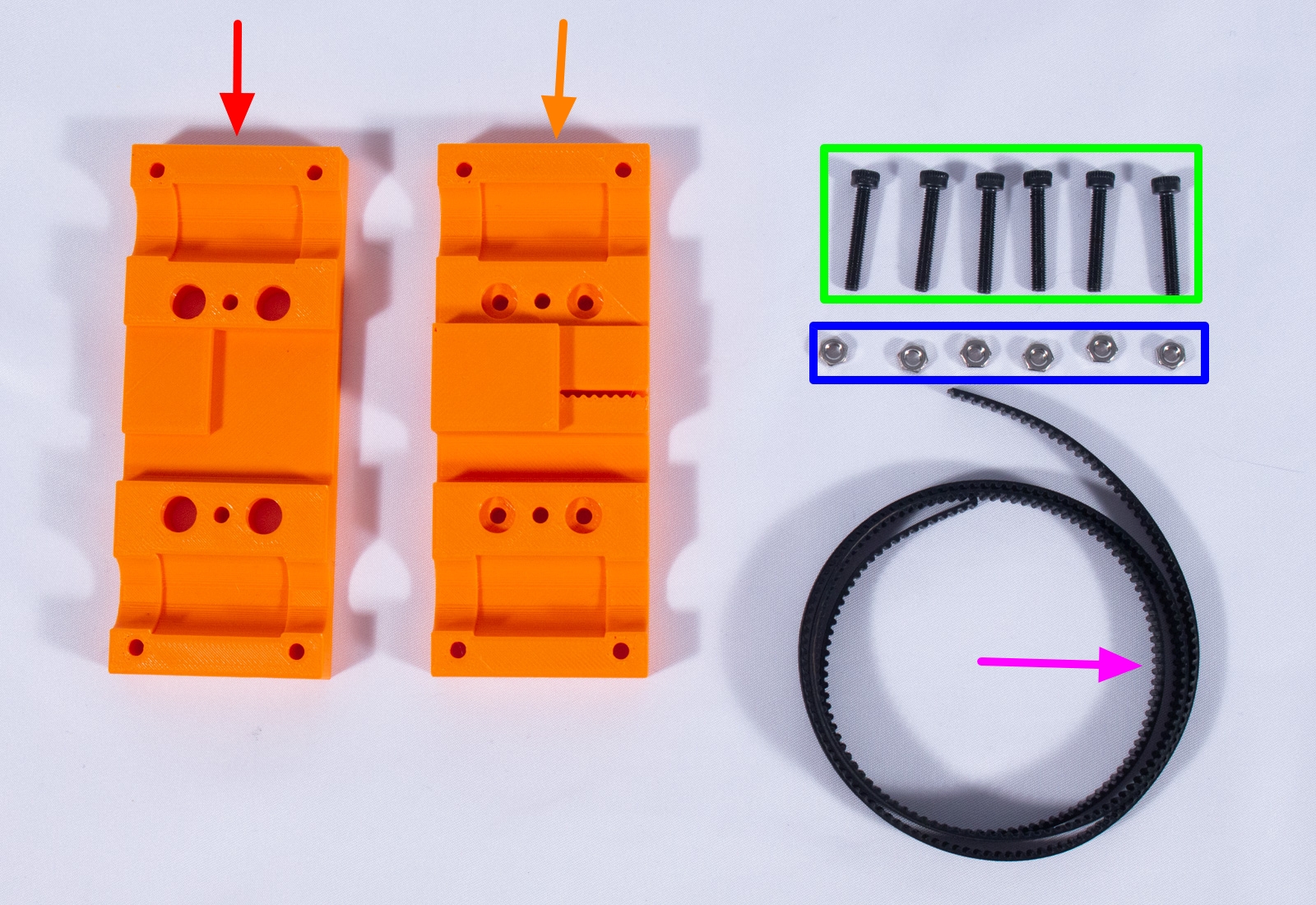
- X_Back_Plate (x1)
- X_Front_Plate (x1)
- GT2 Belt 510mm
- M3 nut (x6)
- M3x20mm bolt (x6)
Assembly

- Insert one end of the GT2 belt into the belt holder in X_Front_Plate as shown. We recommend rolling up the belt at this point and securing it with a zip tie or rubber band. We'll get back to it later.
- Take X_Front_Plate and position it onto one the 2 LMU8 bearings that are on the X-Axis rods.
- Place X_Back_Plate over the bearings ensuring everything mates up nicely with the bearings and X_Front_Plate.
- Insert the M3x20 bolts into each of the 6 holes shown on X_Back_Plate and then insert the nuts into the hexagonal recesses on X_Front_Plate.
- Tighten the bolts, starting with the two in the middle. Then two opposing top and bottom corners. Then the remaining two.
That's all for the X-Axis. Put it aside for now. Have a cookie.