Y-Axis Assembly
Tools Required
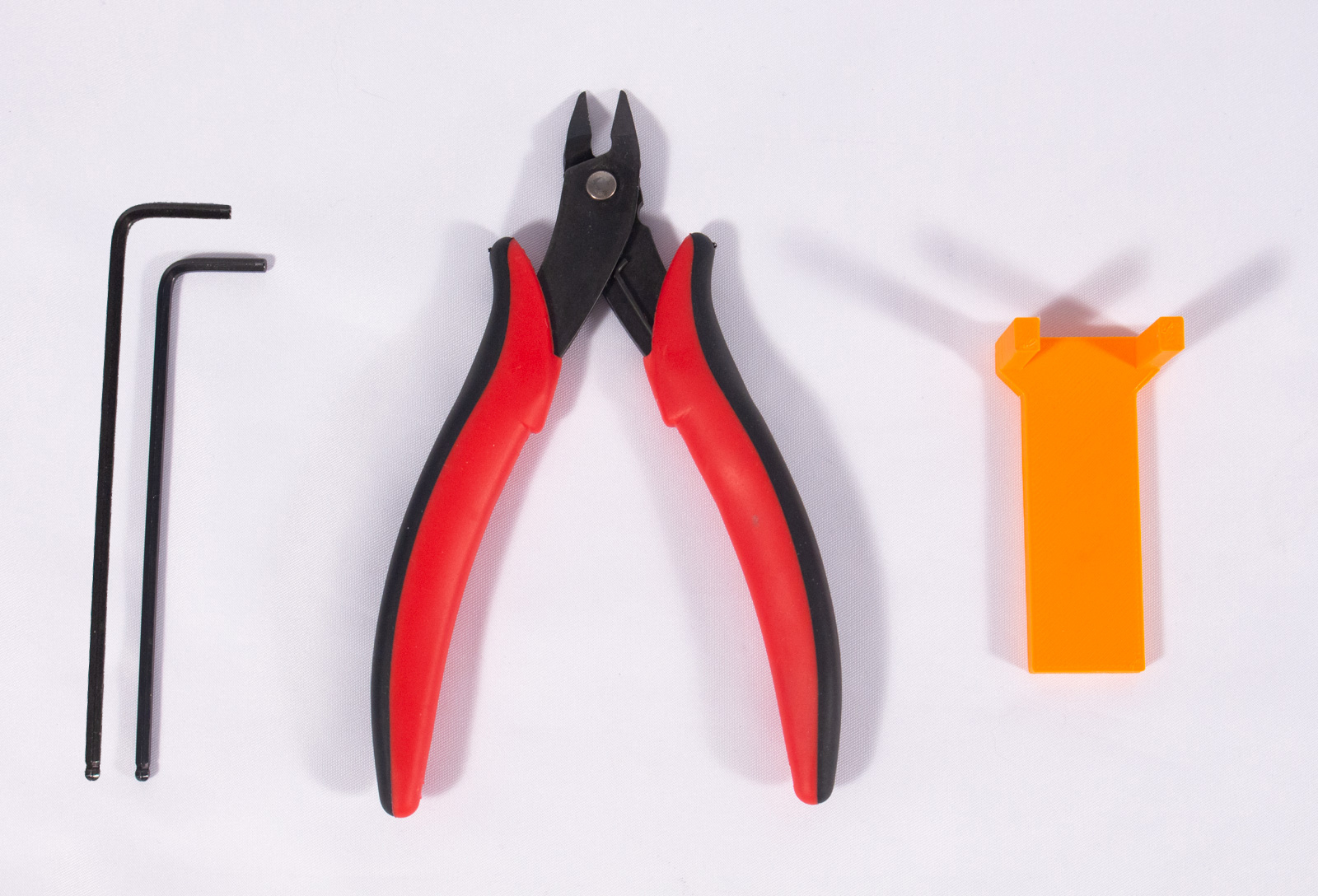
- 2.5mm Hex Key for M3 bolts
- call_split Hex Key for M5 bolts
- 3mm for the kit version
- 4mm for the BOM version
- Snippers for cutting belt
- HeightTool printed part
Mount Y-Axis Rods
Components

Reminder that the M5x10mm bolt and Post Assembly Spring Nuts from the full kit may be visually different than what is shown here but are functionally the same.
- x4_RodHolder (x4)
- M5x10mm bolt (x8)
- Post Assembly Spring Nut (x8)
- 250mm x 8mm Linear Rod (x2)
- M3 nut (x4)
- M3x14mm bolt (x4)
- Previously assembled frame
Mount Rod Holders
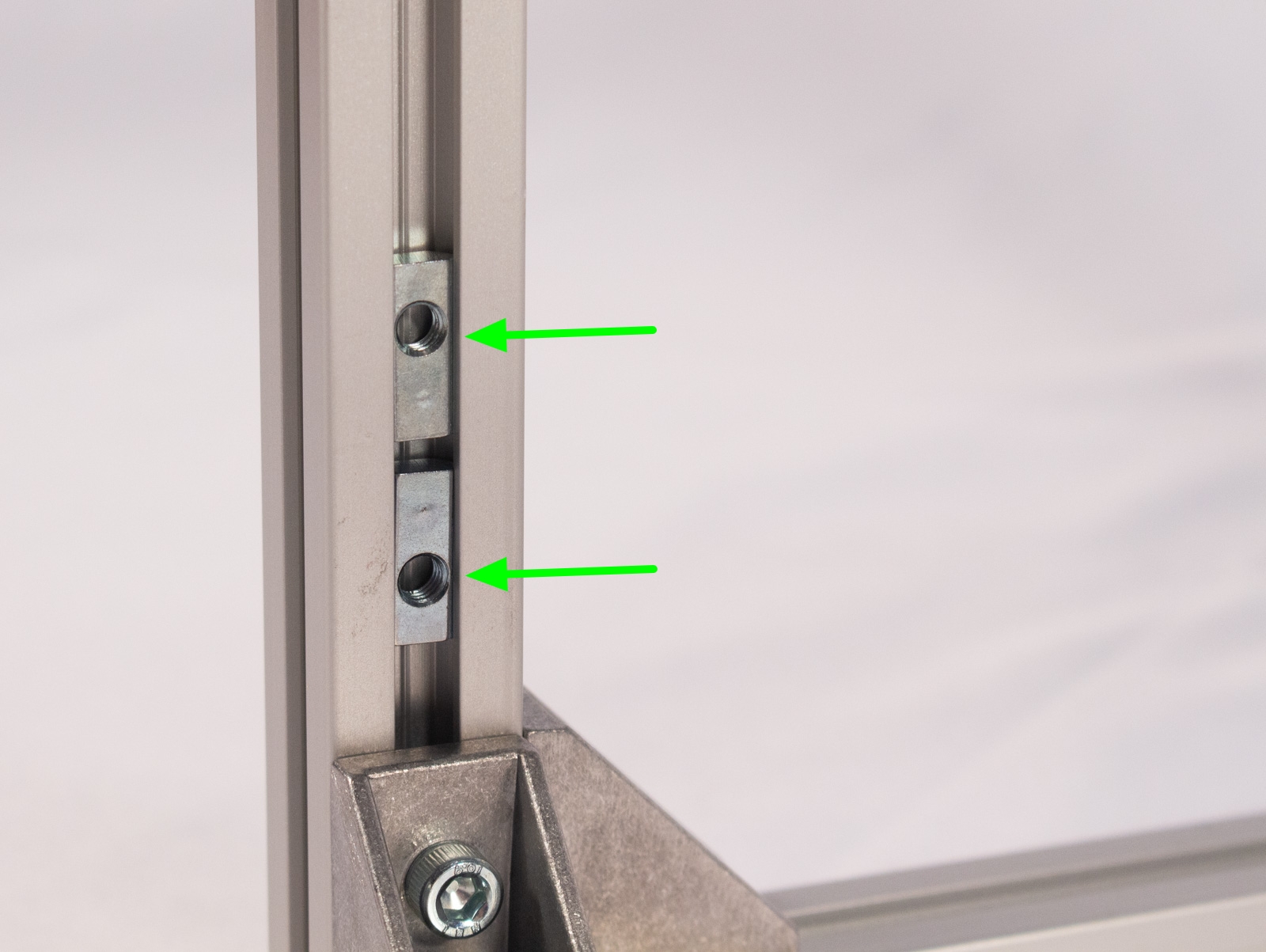

- On each of the upright 200mm extrusions (these are the "Z-axis") insert two of the spring nuts into the channel on the inner edge, as shown. You must make sure that the longer side of each spring nut points inward, as shown in the image. If you do not do this it will block other components later!!!
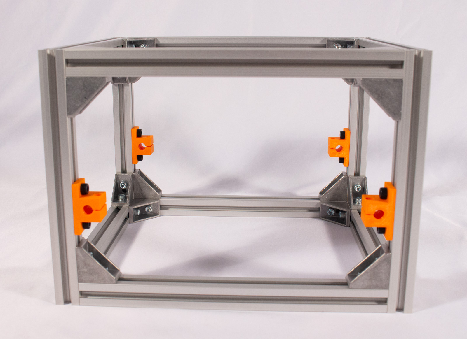
- Insert 2 of the M5x10 bolts into each of x4_RodHolder parts and mate those up on each of the 4 extrusion uprights with the inserted spring nuts. Make sure that the hexagonal recess is facing down on each. Tighten only slightly so they stay on.
- Place the frame on a flat surface again and then take the HeightTool and place as shown under each x4_RodHolder. This will set the same height for all holders (it is 60mm from the bottom of the frame to the bottom of the holder).
- With HeightTool in place tighten both bolts on each of the rod holders to keep them in place.
Insert Rods and Mount X-Axis

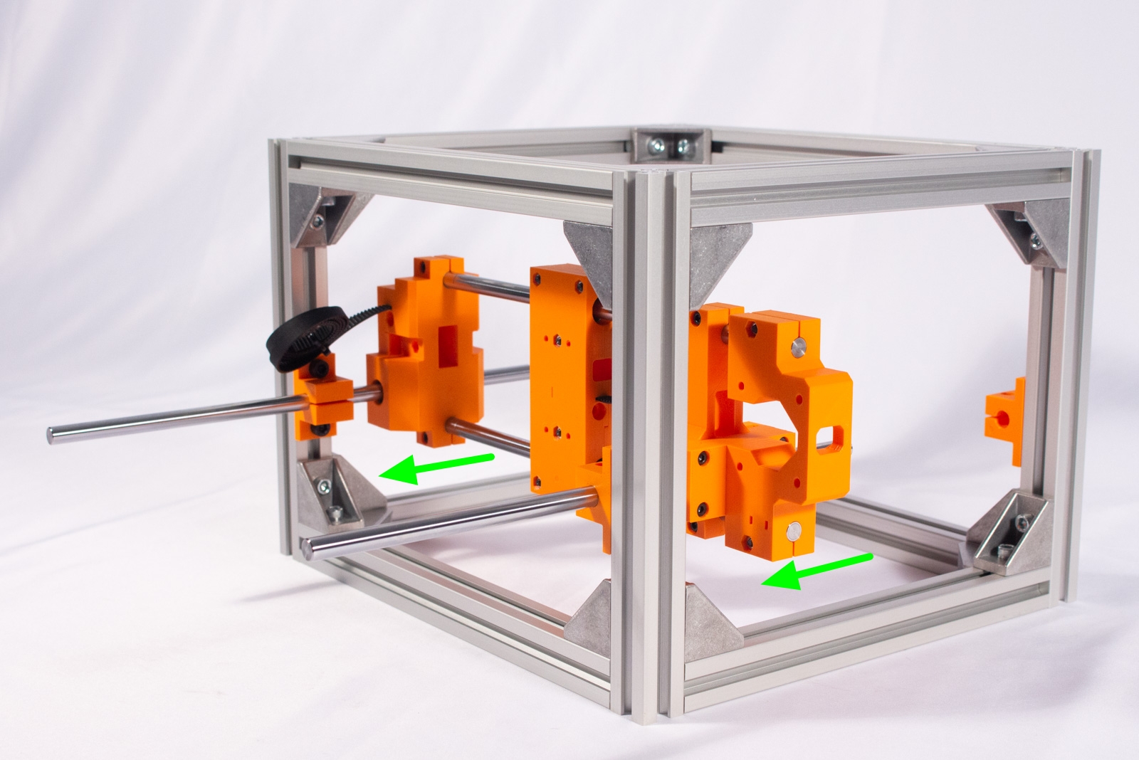


- Take each of the 250mm rods and push them through the rod holders so that the holder is roughly in the middle of the rod, as shown.
- Now take the X-Axis assembly from the previous section and carefully slide the bearings over the rods. As before, this should go on easily and if there is any real resistance double check that everything is lined up properly. Be careful so that you do not push any of the bearing balls out.warning Be very careful on the above step! If you feel any real resistance to the rods being inserted into the bearings DO NOT FORCE IT. Recheck that everything is parallel. We even suggest taking one of the Y axis rods out and trying to insert it into the bearings on each side of the X axis individually. If there is any resistance those bearings may not be properly aligned. In general, just take your time here, don't force anything, and ensure you don't loose any bearing balls.
- With the X-Axis assembly on the rods continue to push the rods towards the back of the machine and into the rear rod holders. Make sure that the ends of the rods wind up being flush with the outer faces of the rod holders front and back.
- Now insert an M3x15 bolt and M3 nut into each of the holders (the nut goes in the hexagonal recess that should have been aligned facing down) and tighten just enough so the rods can no longer move. Use the short side of the hex key for leverage. Do not overtighten these bolts.
Movement Checks
- Before moving onto the next section, take a minute to ensure the Y-Axis is moving well.
- Move the X-Axis assembly back and forth along the Y-Axis rods. It should move smoothly without binding.
- If it moves better in the middle than at the ends or "bounces back" when moved to one end it likely means the rods are not perfectly parallel. Follow the below procedure:
- Move the Y-Axis to the end that is binding.
- Undo the two bolts on one of the rod holders slightly so that it can move.
- Move the assembly back and forth along the Y-Axis rods a few times settling back on the side it was binding.
- Now re-tighten the two bolts.
- If still binding on that side do the same for the other rod holder on that end of the Y-Axis.
- Check the other side to make sure it's not binding there. If it is, repeat the above process but on that side of the Y-Axis.
- If it is still binding please head over to the forum for troubleshooting.
Movement in 2 axis is half the battle! Now to make it move under its own power...