Motors and Belts
Tools Required
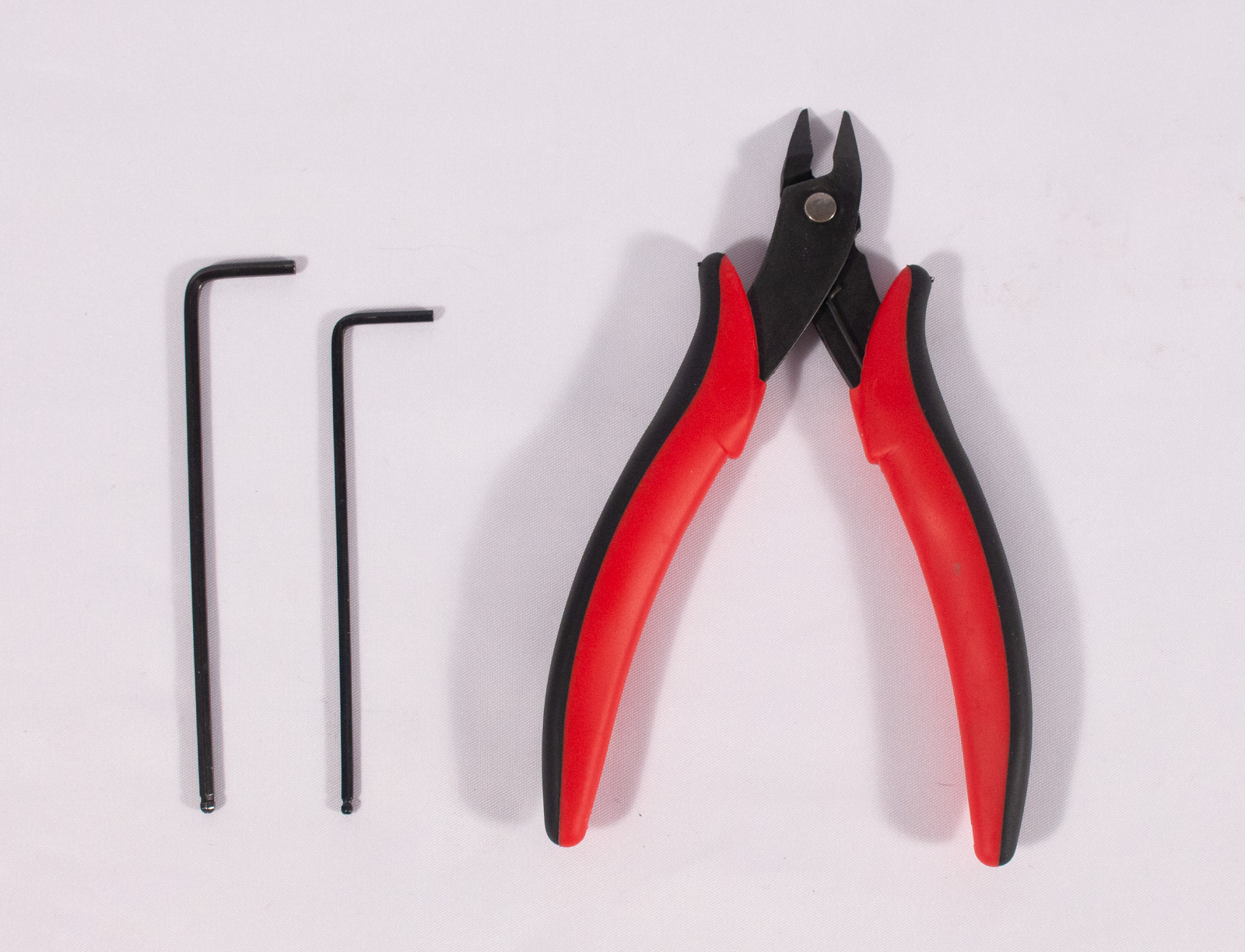
- call_split Hex Key for M5 bolts
- 3mm for the kit version
- 4mm for the BOM version
- 2.5mm Hex Key for M3 bolts
- call_split Hex Key for set screws
- 1.5mm for the kit version
- 2mm for the BOM version
- Snippers for cutting belt
Y Motor
Components
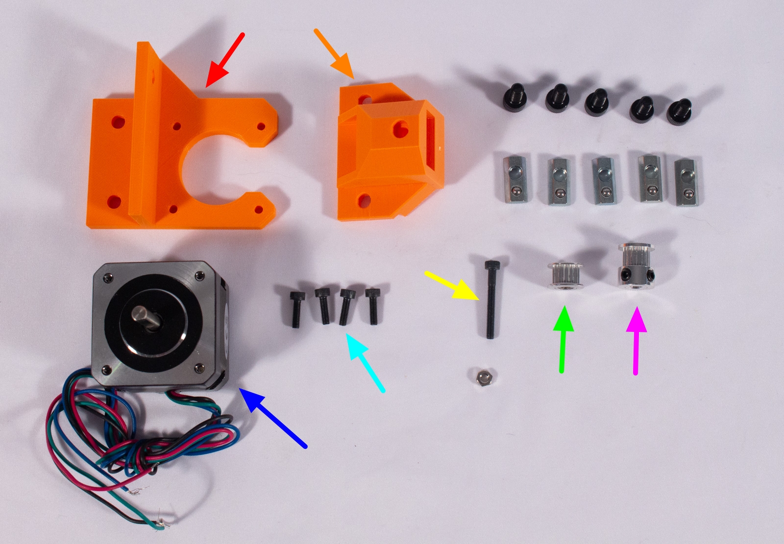
- Y_Motor_Mount (x1)
- Y_Pulley_Mount (x1)
- M5x10mm bolt (x5)
- Post Assembly Spring Nut, HNTP5-5 (x5)
- GT2-16 3mm Bore Idler Pulley (x1)
- GT2-16 5mm Bore Drive Pulley (x1)
- NEMA 17 Stepper Motor
- M3x10mm bolt (x4)
- M3x25mm bolt (x1)
- M3 nut (x1)
call_split The motors that come with the full kit already have terminated cable ends unlike the BOM version which are just bare wires. This is ok and will be covered in the next step.
Mount Y Motor
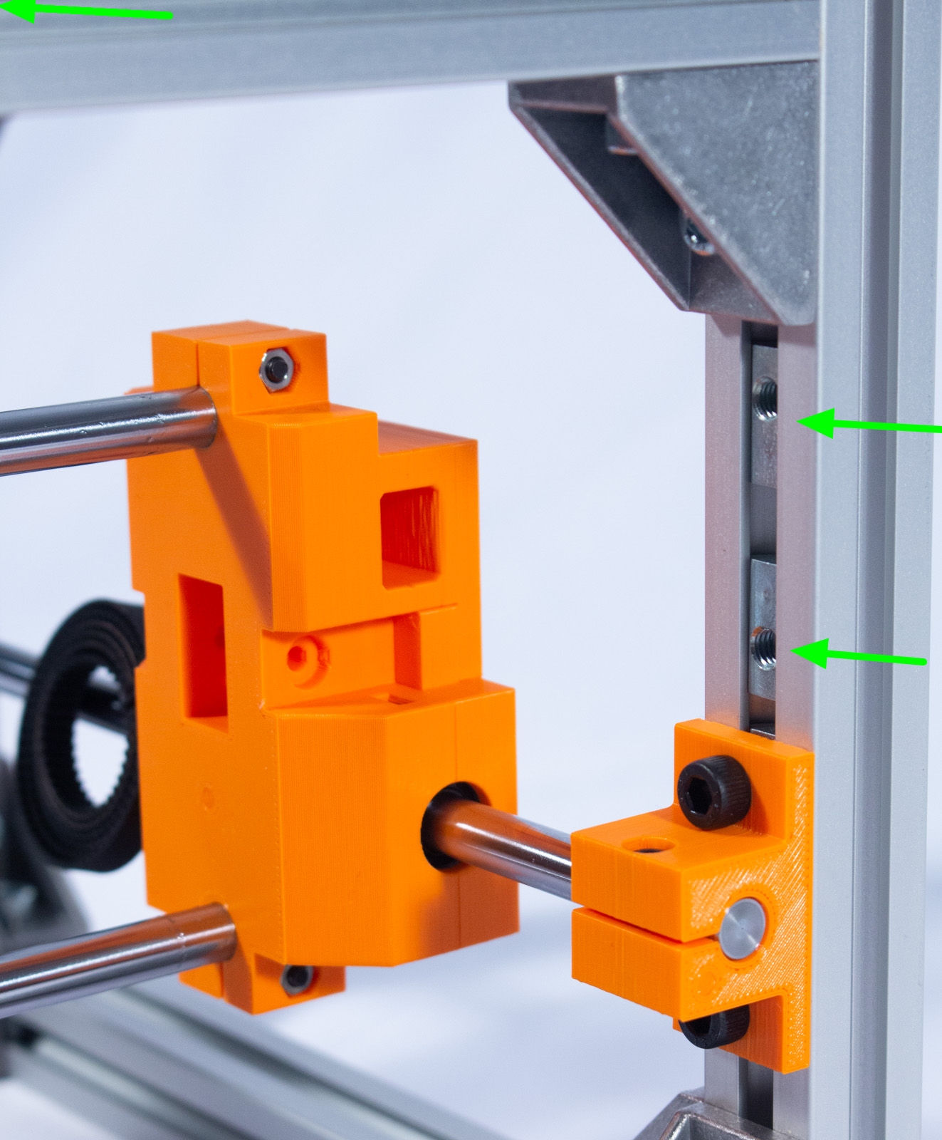
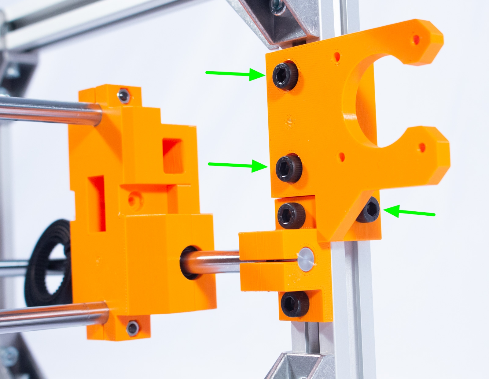
- On the back, drive-side of the machine mount Y_Motor_Mount so that it is sitting directly on top of the rod holder, as shown, using 3 pairs of M5x10mm bolts and spring nuts. Note that the 2 spring nuts on the inside channel of the extrusion need to be inserted in the orientation shown.
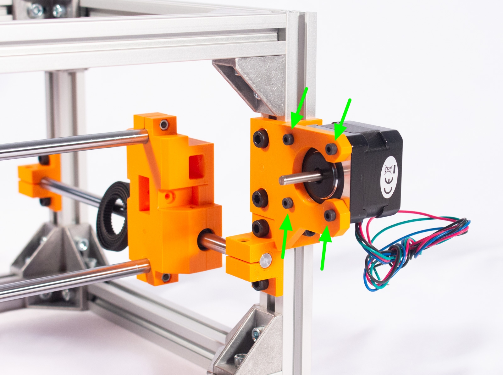
- Using the 4 M3x10 bolts, mount the NEMA 17 stepper motor to the mount ensuring that the wires coming out of the motor are facing down. Wrap these up to keep them out of the way for now.
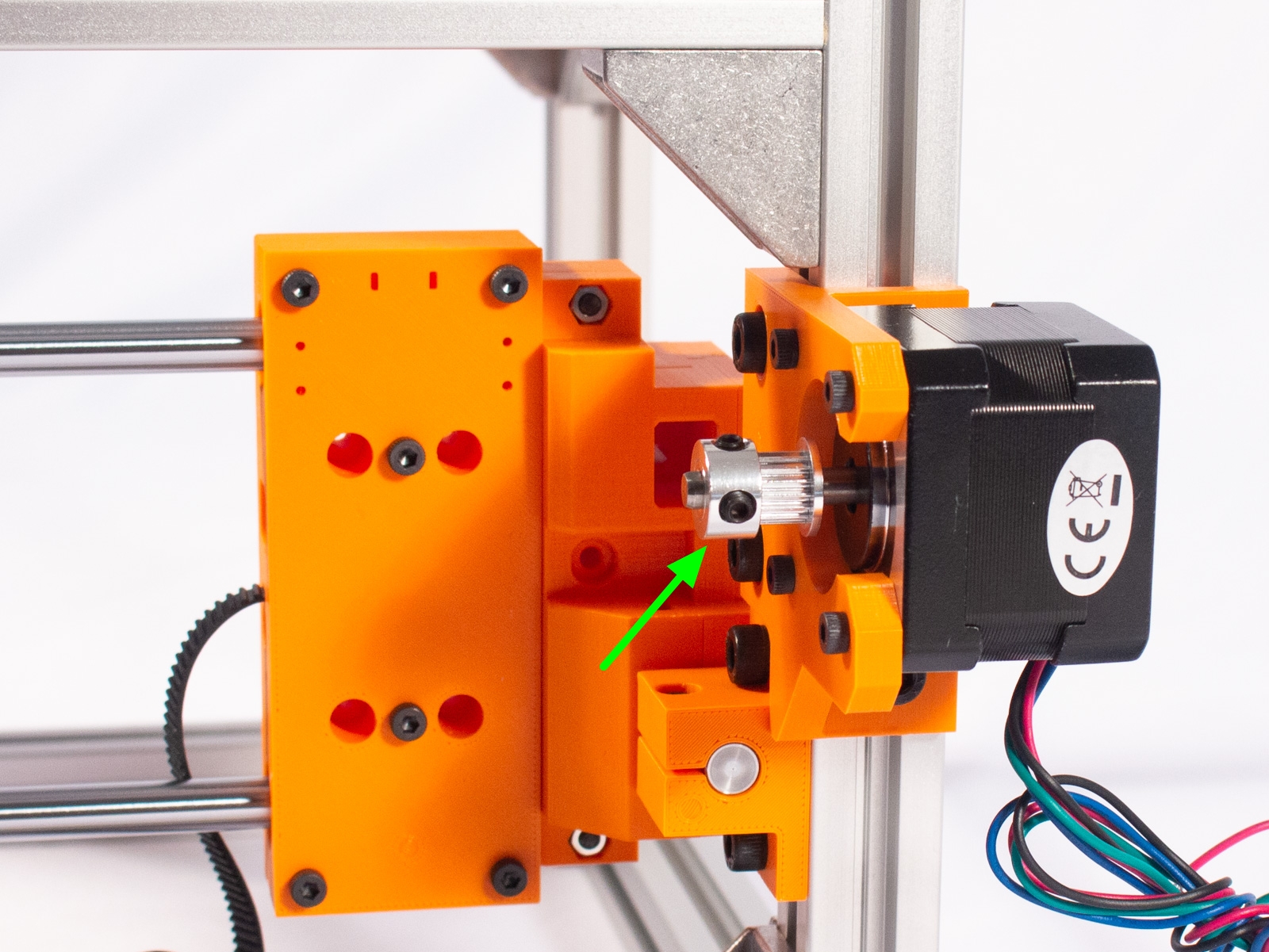
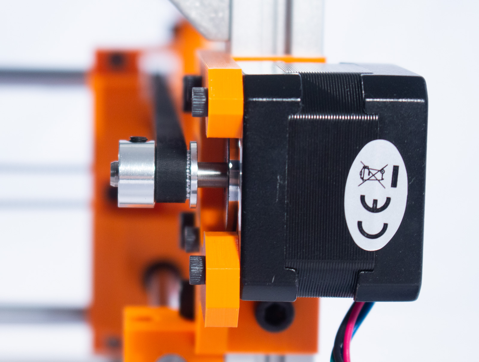
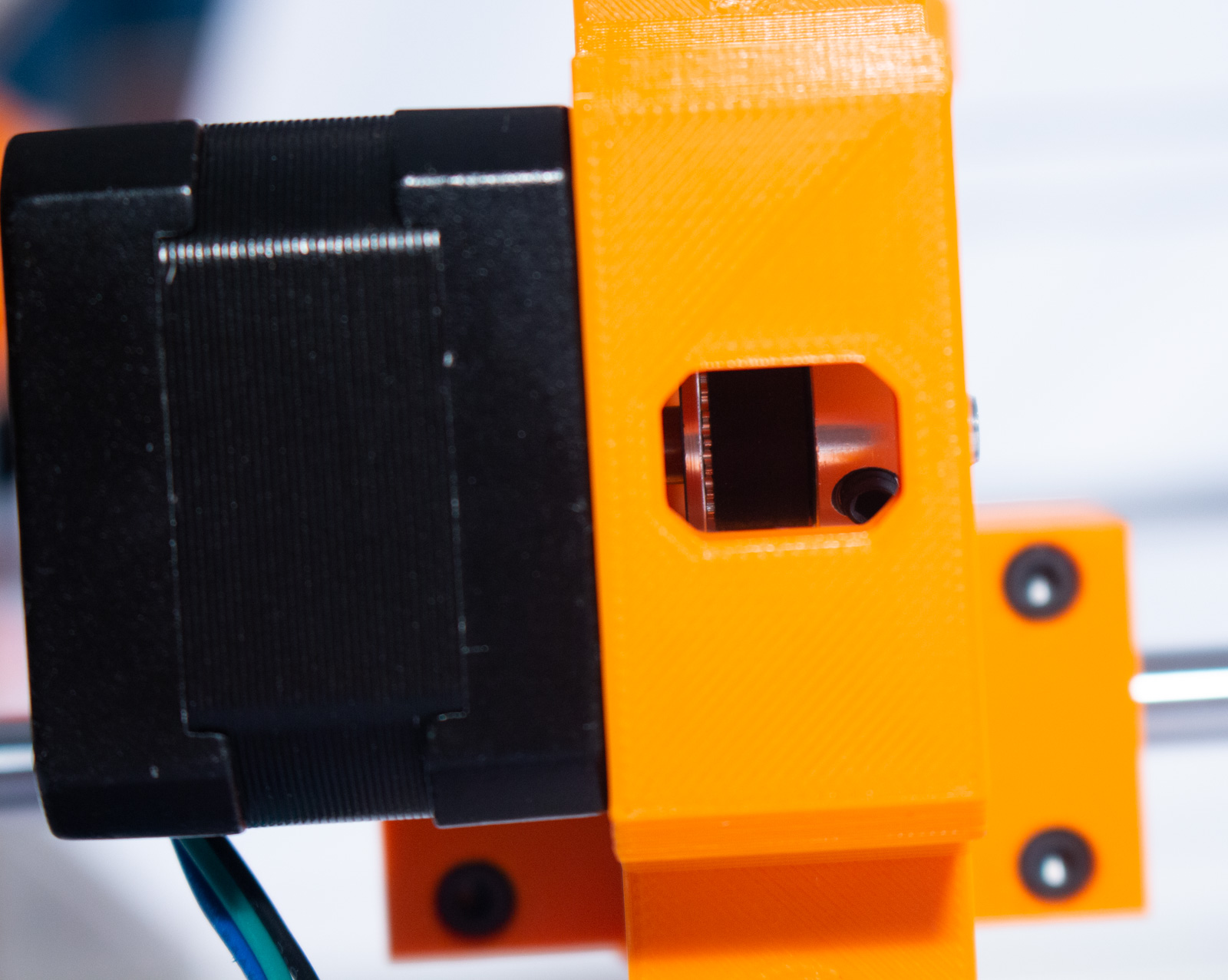
- Slide the GT2-16 drive pulley over the motor shaft, as shown, so that one of the set screws is aligned with the flat edge on the shaft. Only lightly tighten that one set screw for now.
Mount Y Idler Pulley
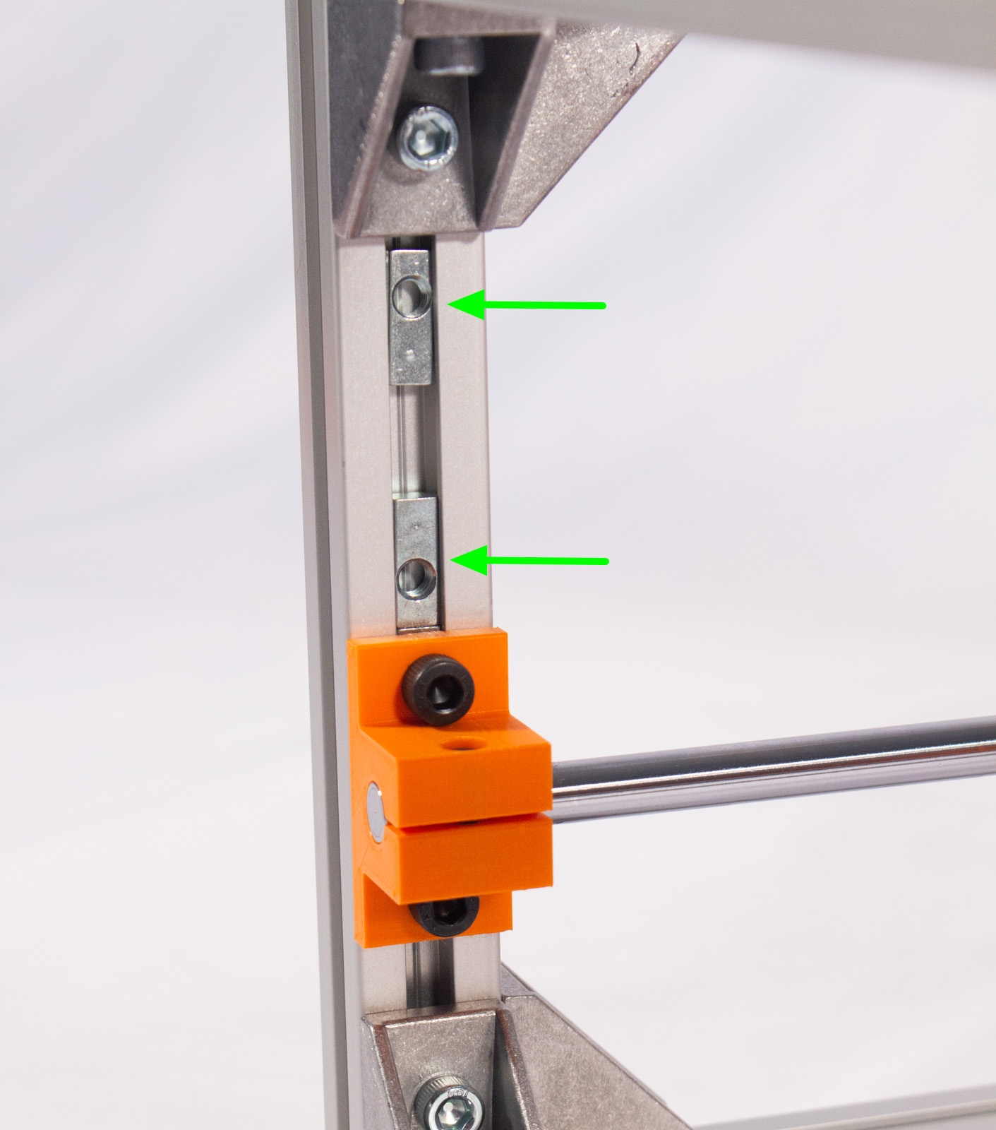
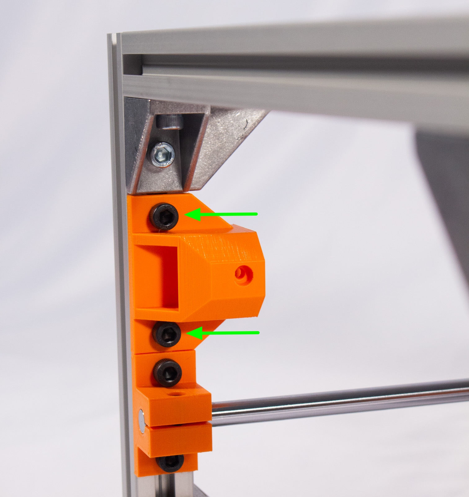
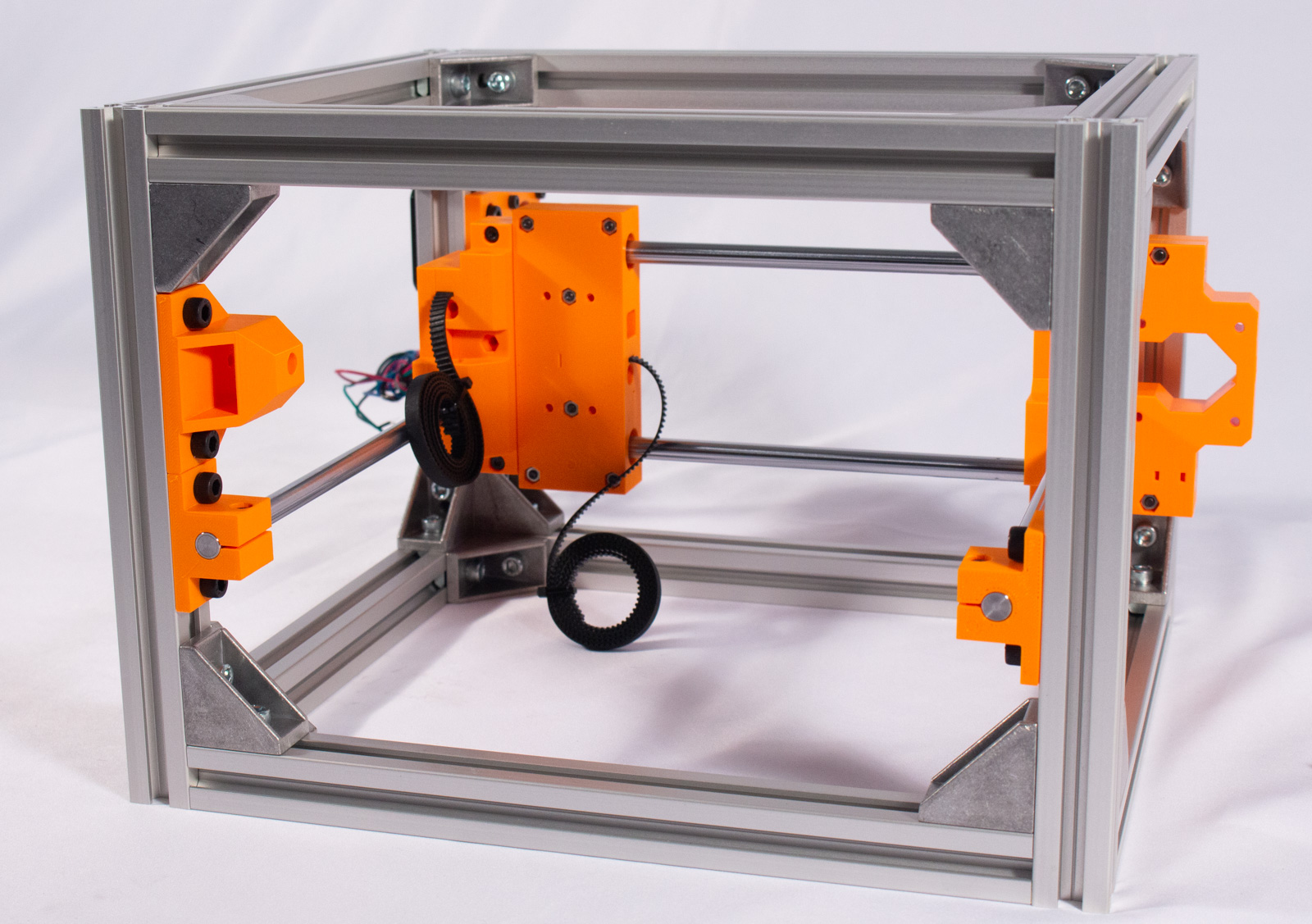

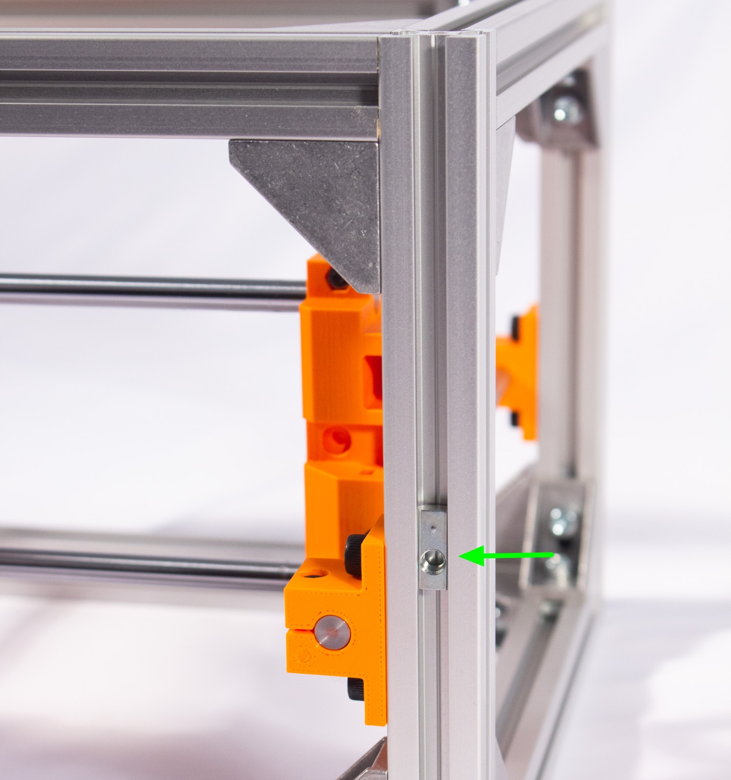
- One the front, drive-side of the machine mount Y_Pulley_Mount so that it is sitting directly on top of the rod holder, as shown, using 2 pairs of M5x10mm bolts and spring nuts. Note that the 2 spring nuts need to be inserted in the orientation shown.
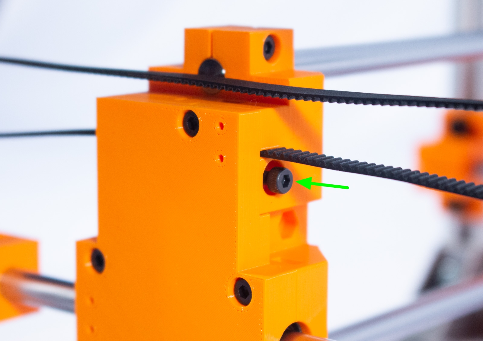
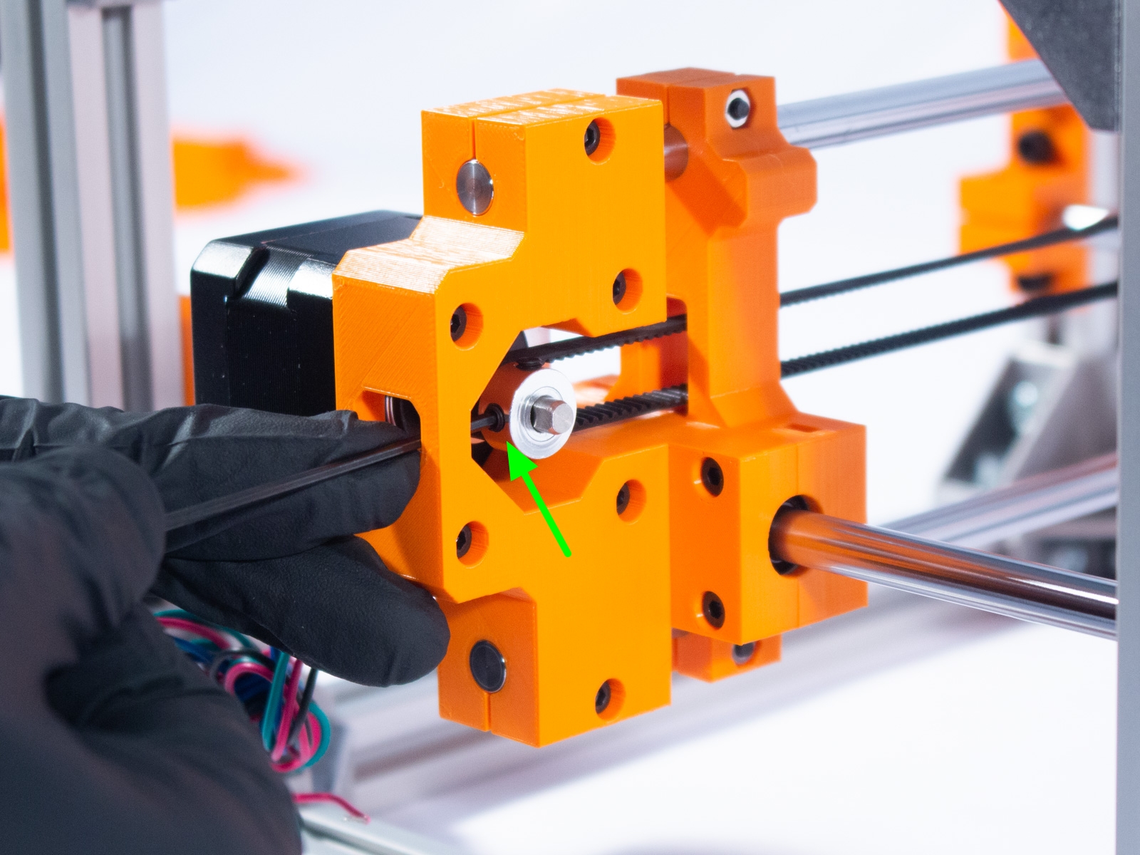
- Place the GT2-16 idler pulley into the mount and pass the M3x25 bolt through it, then secure with a nut inserted into the hexagonal recess. Tighten until finger tight.
Y Belt
Components
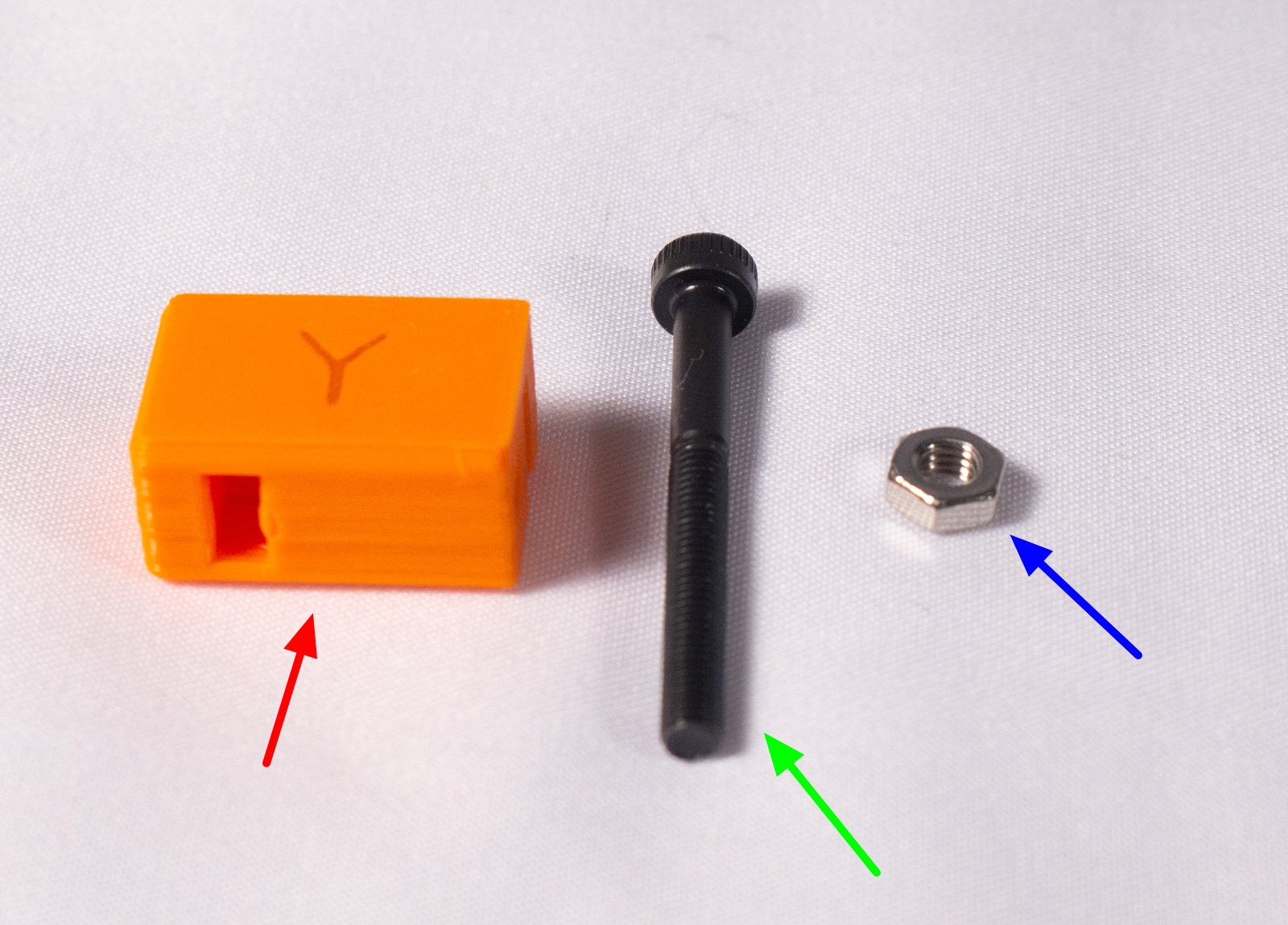
- Y_Tensioner (x1)
- M3x30mm bolt (x1)
- M3 nut (x1)
Assembly


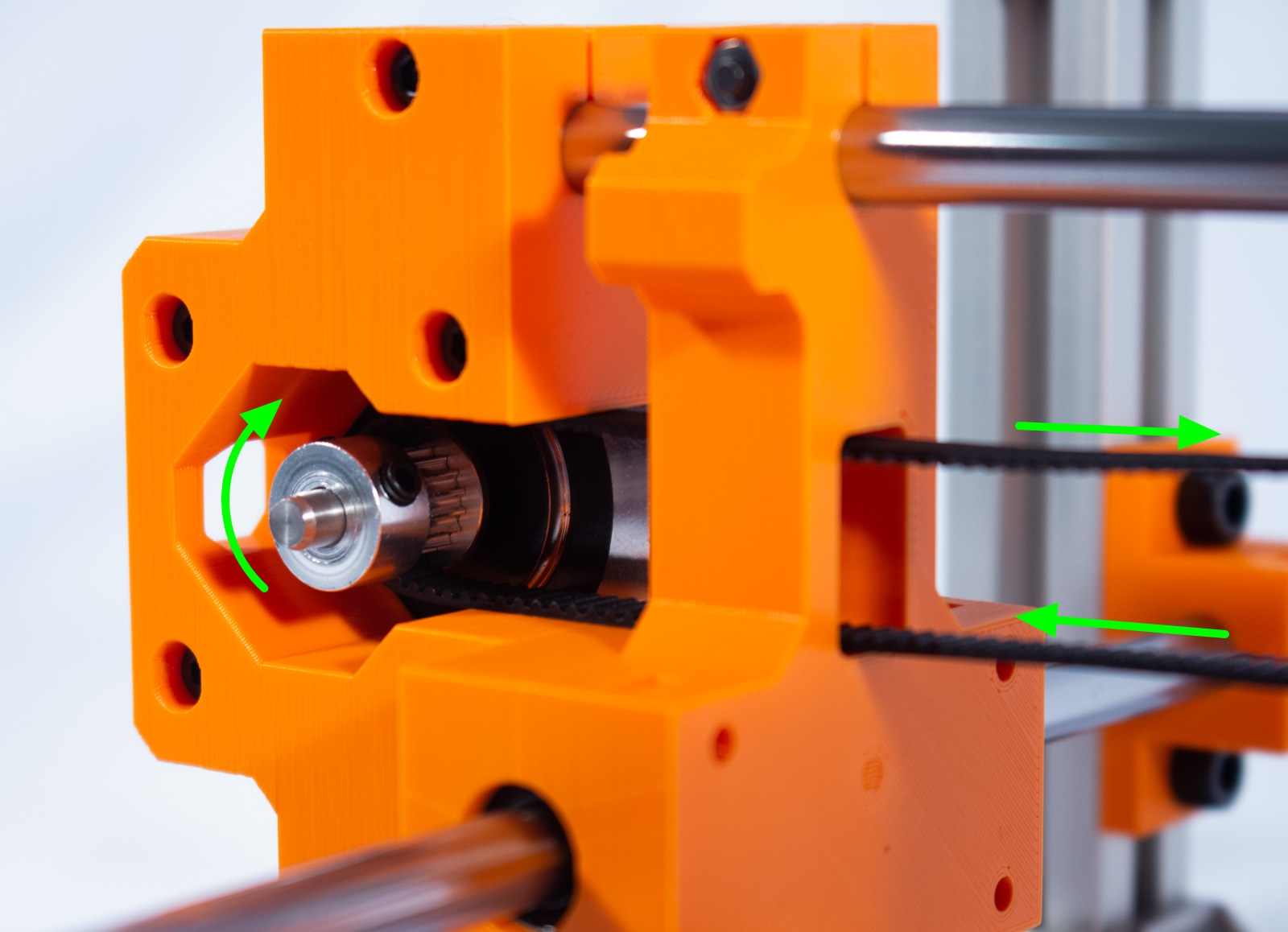
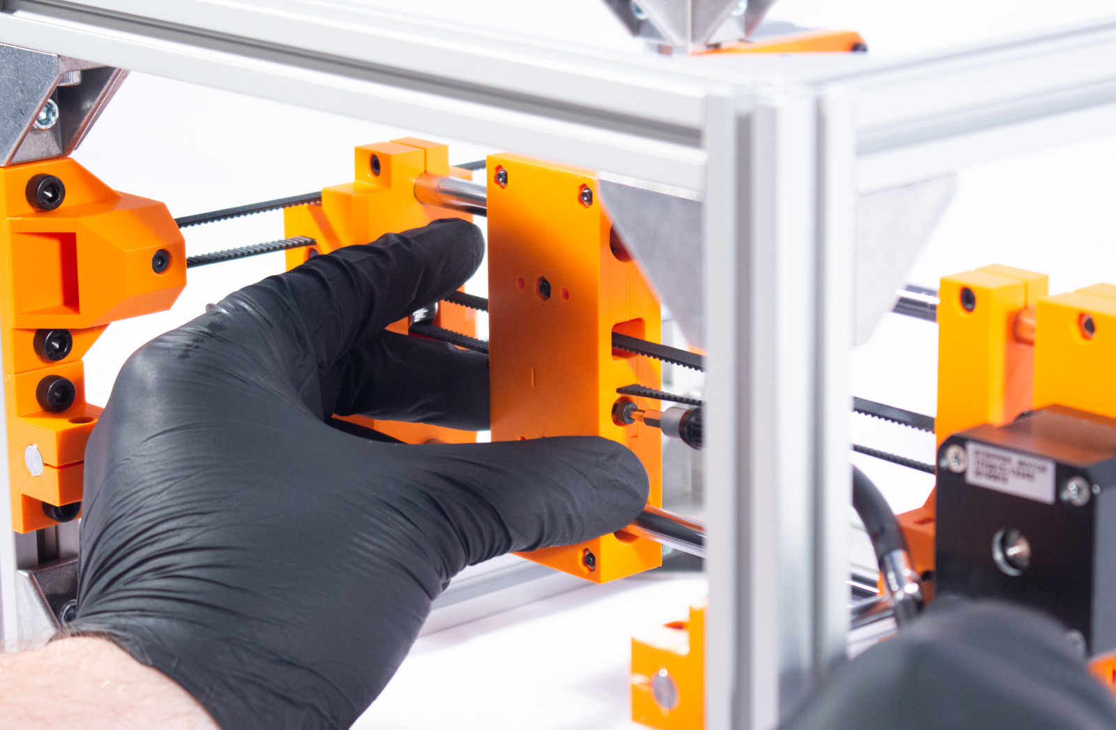
- Take the belt inserted into Y_Drive_Main and run it through the idler pulley as shown then back to the motor and around the drive pulley, as shown.
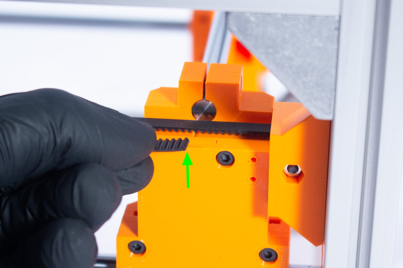
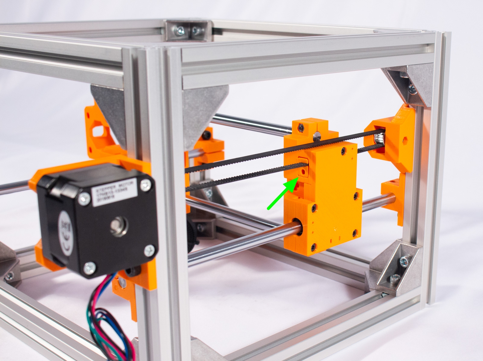
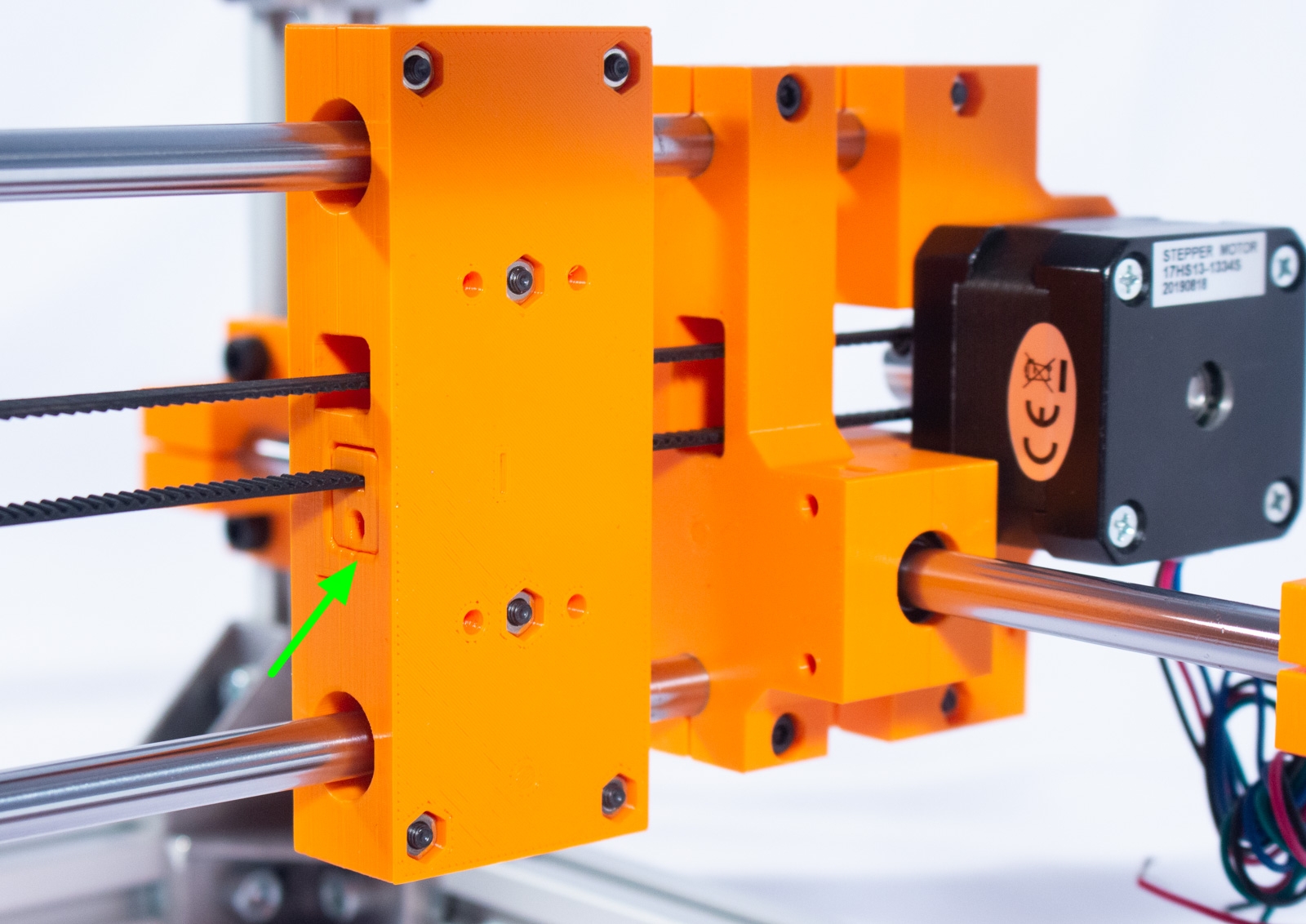
- Slide the X-Axis assembly to the front (away from the motor) and pull the belt tight. Holding it over the Y-Axis drive block there is a marking on the top showing where the belt needs to be cut. Cut the belt with the snippers where it meets that mark.
- Now insert the end of the belt all the way into Y_Tensioner (note that this tensioner is marked with a Y and is a mirror of the X_Tensioner).
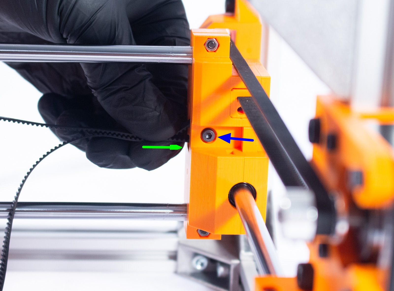
- Insert the M3 nut into the slot in the tensioner and then insert it into the Y-Axis block as shown, making sure the nut doesn't fall out.
- Now insert the M3x30mm bolt into the other side and turn until it grabs onto the nut and starts pulling the tensioner block in. DO NOT fully tension it at this point. We will come back to that.
X Motor and Belt
Components

- GT2-16 3mm Bore Idler Pulley (x1)
- GT2-16 5mm Bore Drive Pulley (x1)
- NEMA 17 Stepper Motor
- X_Tensioner (x1)
- M3x20mm bolt (x4)
- M3x25mm bolt (x1)
- M3x30mm bolt (x1)
- M3 nut (x2)
Mount X Motor
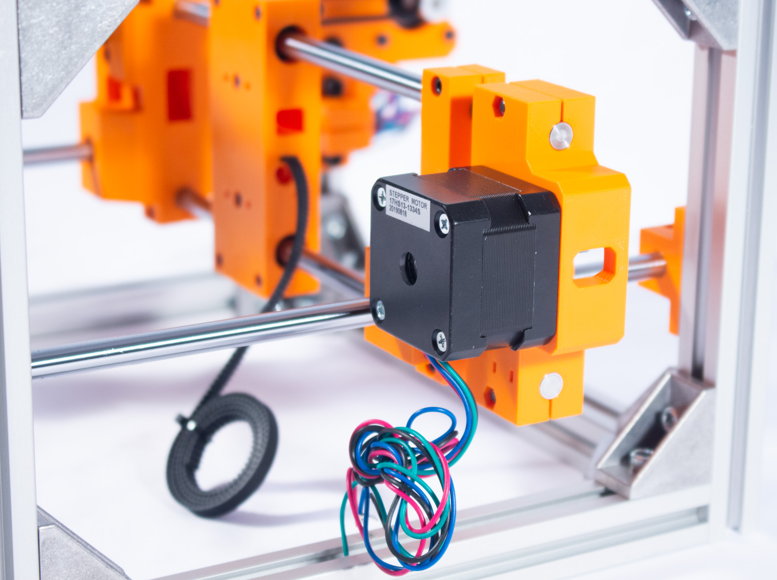
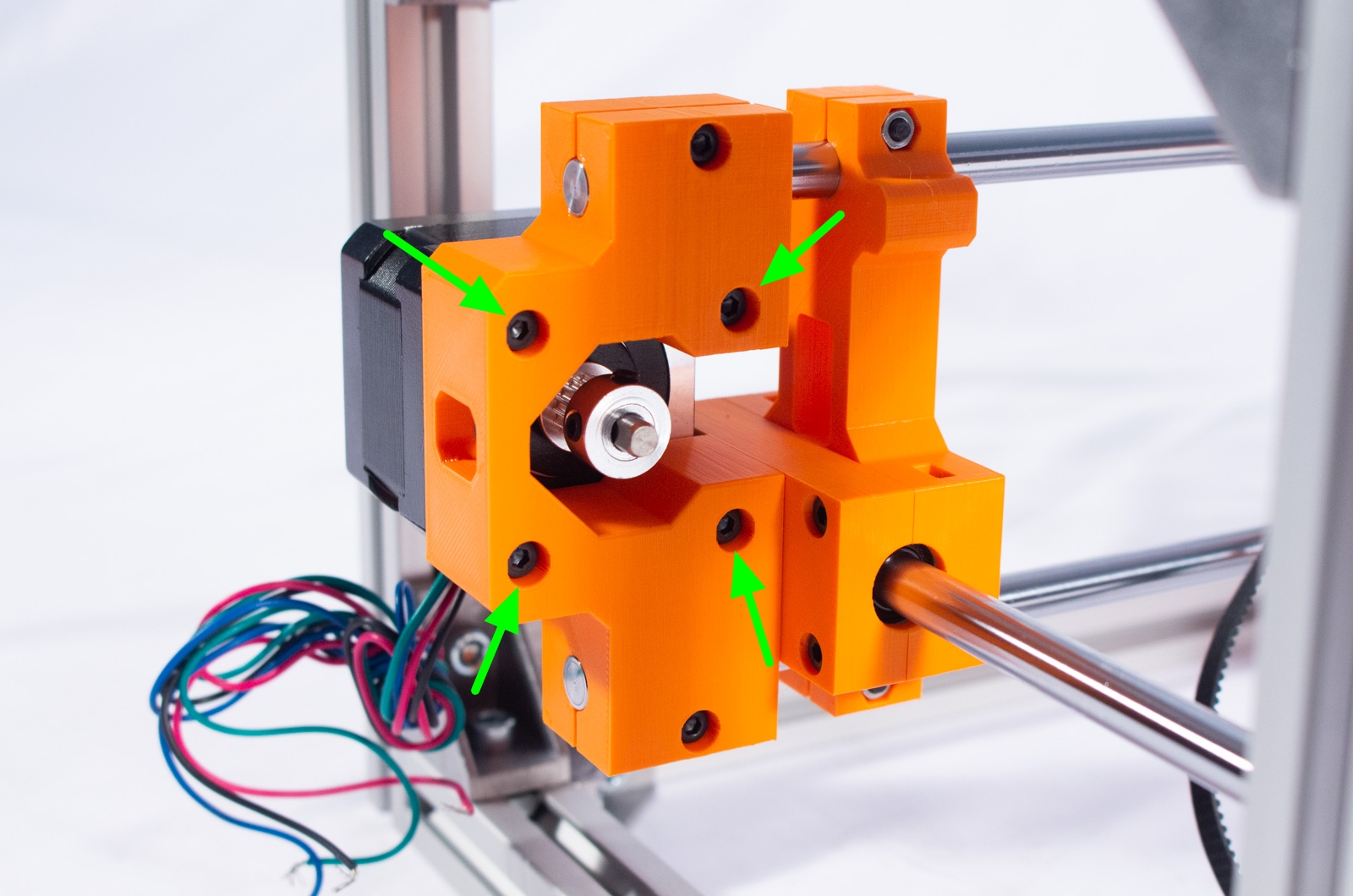
- Mount the NEMA 17 stepper motor to X_Motor_Mount using the 4 M3x20 bolts, as shown, ensuring that the wires coming from the motor are facing down. Wrap these up to keep them out of the way for now.
- Slide the GT2-16 drive pulley over the motor shaft, as shown, so that one of the set screws is aligned with the flat edge on the shaft. Only lightly tighten that one set screw for now.
Mount X Idler Pulley

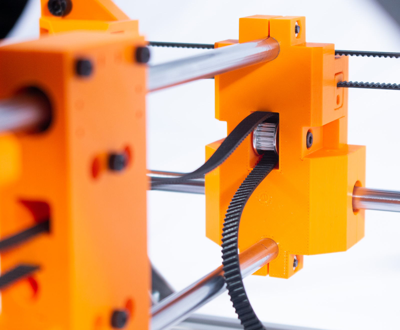
- Take the belt inserted into the X-Axis carriage and loop it around the GT2-16 drive pulley and then back to the idler pulley side, through the channel in the X carriage.
- Loop the belt around the idler pulley pinch the belt to keep it there. Then insert the pulley with the belt into the pulley mount on Y_Drive_Main and pass the M3x25mm bolt through it, then secure with a nut inserted into the hexagonal recess. Tighten until finger tight. (You can technically install the pulley first then run the belt through, but we found this to be easier).
X Belt

- Move the X-Axis carriage all the way towards X-Axis motor you just installed, then pull the belt back towards the X-Axis carriage, holding it tight against the back of there carriage where you will see another small mark. Cut the belt at this mark.
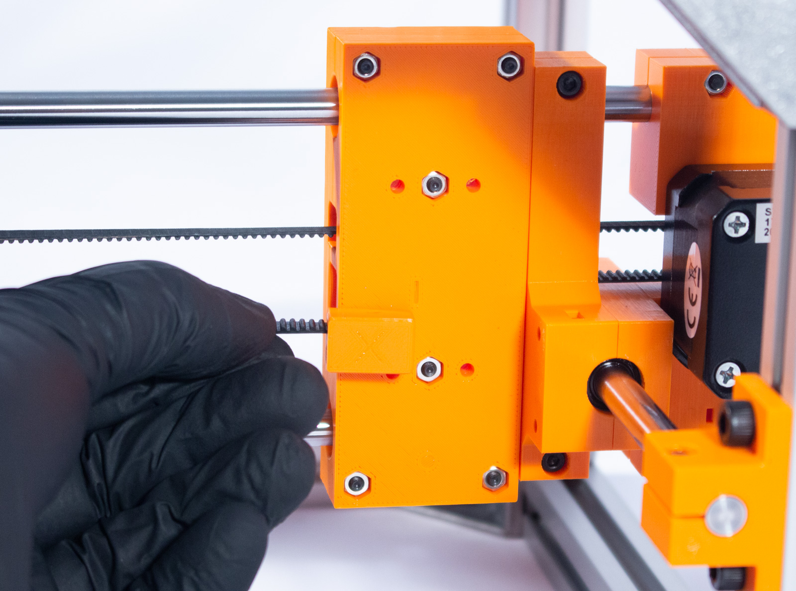
- Now insert the end of the belt all the way into X_Tensioner (note that this tensioner is marked with an X and is a mirror of the Y_Tensioner).
- Insert the M3 nut into the slot in the tensioner and then insert it into the X-Axis carriage as shown, making sure the nut doesn't fall out.
- Now insert the M3x30mm bolt into the other side and turn until it grabs onto the nut and starts pulling the tensioner block in.
Tensioning
- Go back to the Y-Axis belt and now use the 2.5mm hex key to turn the M3x30mm tension bolt just enough so that the belt will turn the motor drive pulley when the carriage is moved around.
- Look down the top of the belt and ensure that both top and bottom are completely in alignment. If they are not loosen the drive pulley set screw and slide the pulley along the shaft until both top and bottom belts are aligned.
- Tighten both set screws on the pulley. You may have to move the carriage so the pulley turns exposing the other set screw.
- Now continue to turn the tension bolt. You want the belt to be tight enough that it provides some resistance when trying to press both sides of the belt together with 2 fingers. The belt should remain straight on its own and not sag under it's own weight. If plucking the belt produces a high pitch note it is likely too tight.
- If the tensioner block bottoms out before it's properly tight, just unscrew the M3x30mm bolt all the way, remove the belt from the tensioner block, snip of 1-2 of the teeth, re-insert and try again.
- If the tensioner block is still sticking out of the main body when fully tensioned, unscrew the M3x30mm bolt all the way, remove the belt from the tensioner block, and then re-insert it a couple teeth further back and try again. You need to be contacting at least 4 teeth on the tensioner block.
- Now repeat the above with the X-Axis. Note: You will need to use the small access hole in X_Motor_Mount to reach the set screws.
Almost there! Have a snack and head on to the next step.