Running Cables
Tools Required
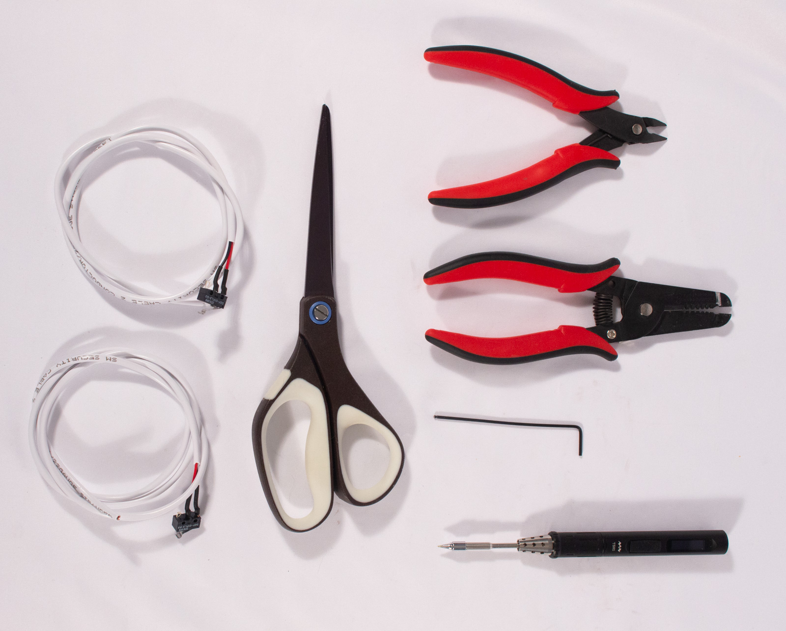
- 1.5mm Hex Key for M2 bolts
- call_split Soldering Iron (not needed for kit version)
- Wire strippers
- Wire snips
- Scissors
Install Limit Switches
The Engravinator can accommodate 2 limit switches per axis but this is largely unnecessary and requires more complicated wiring. Therefore it is for advanced users only and the process will not be described here. We rely on software to inform the engraver where the end opposite the zero-stop is later.
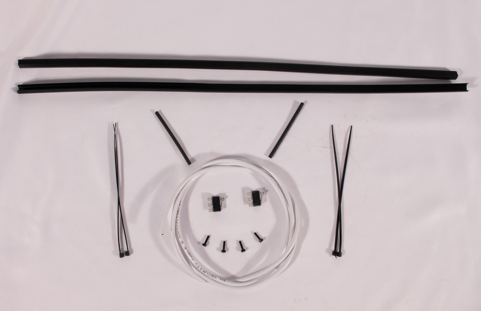
Components
- Limit Switches (x2)
- call_split 2-conductor wire ~900mm (x2) (this is pre-installed on the kit version)
- M2x8mm bolt (x4)
- call_split Heat shrink tube (not needed for kit version)
- Zip ties
- Slot Cover
Solder Wires to Switches
call_split If you purchased a full kit it came with pre-soldered switches and you can skip this step.
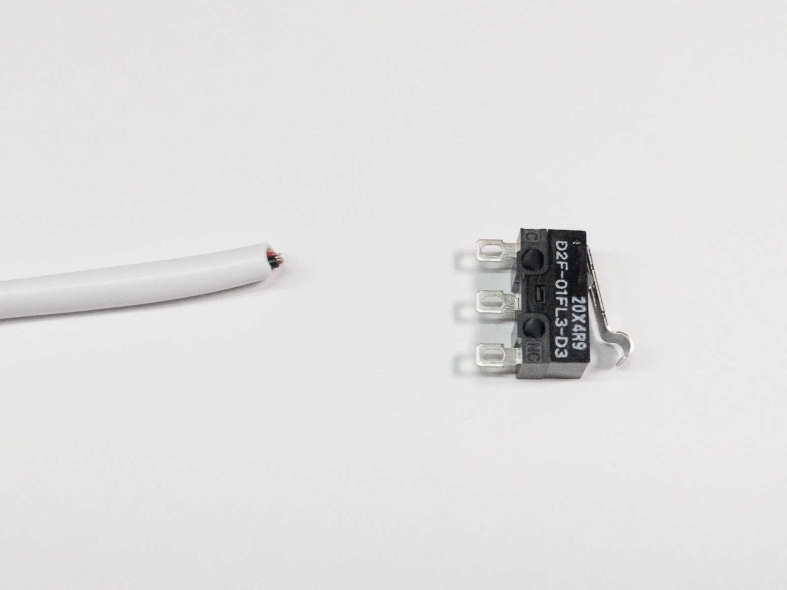
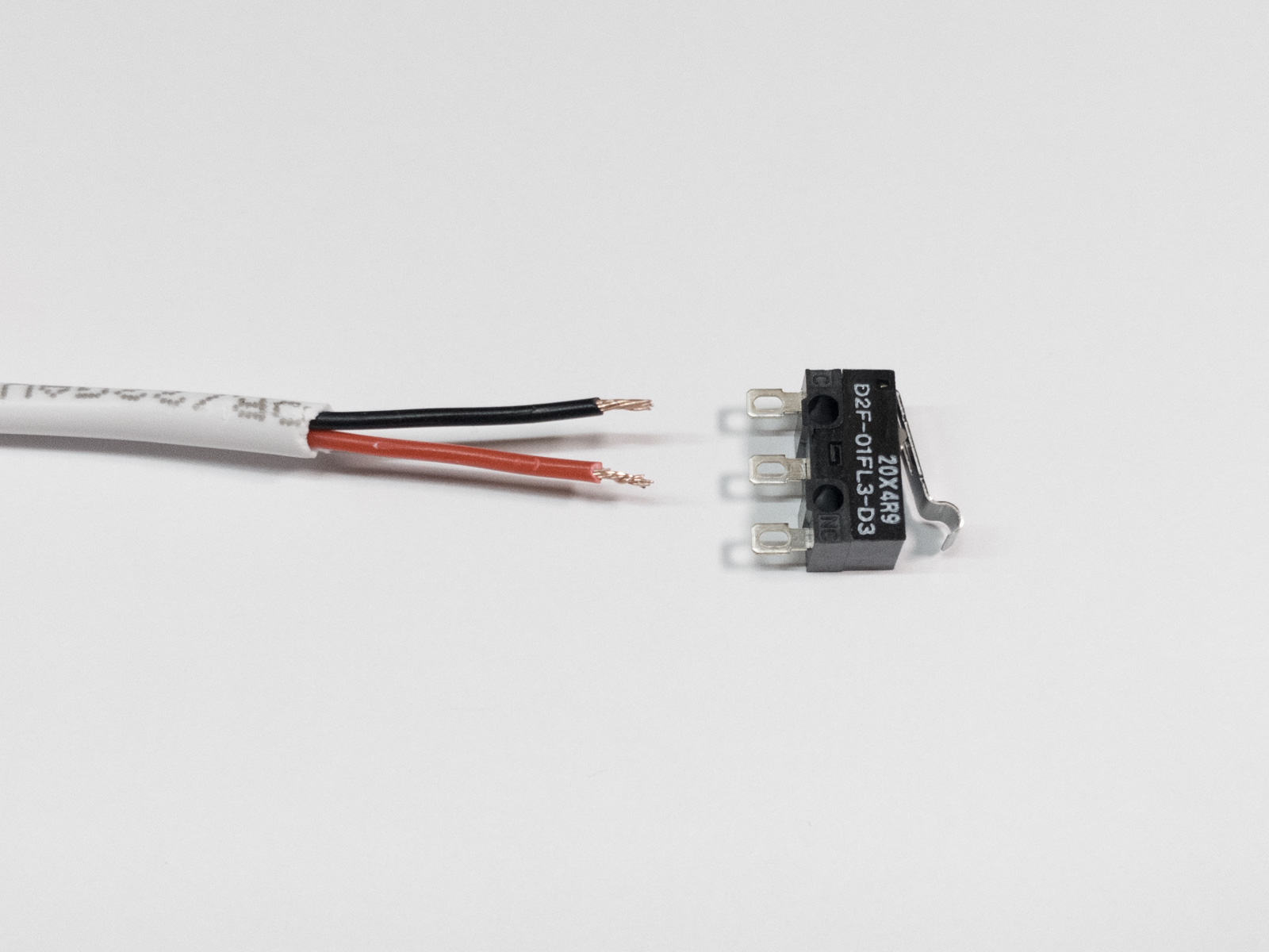
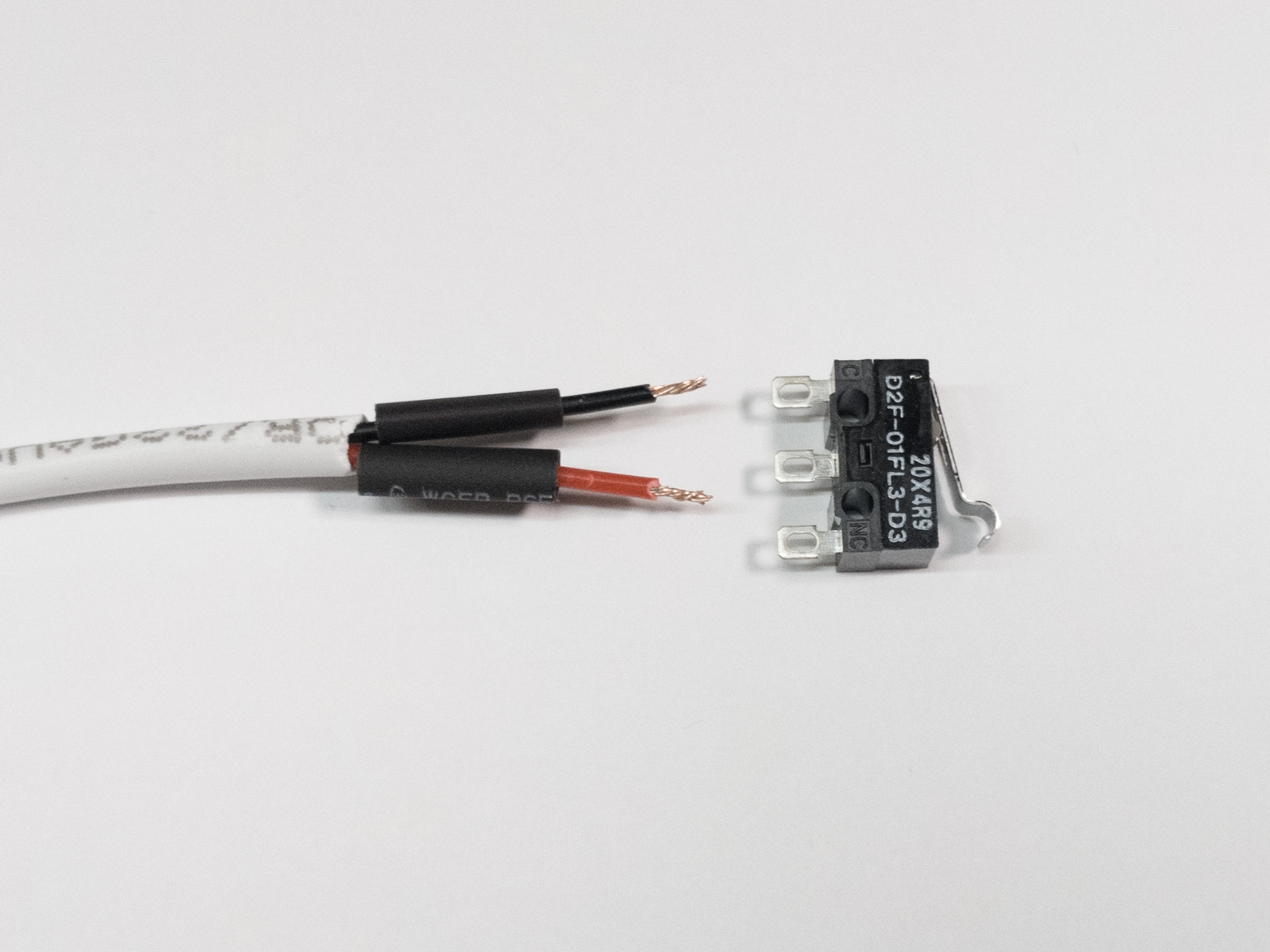
- If your 2-conductor wire includes an outer sheathing, remove about 20mm of that covering.
- Use the wire strippers to strip ~5mm from the end of each wire (just on the one end for now).
- Slide a 10mm length of heat shrink tubing over each wire.
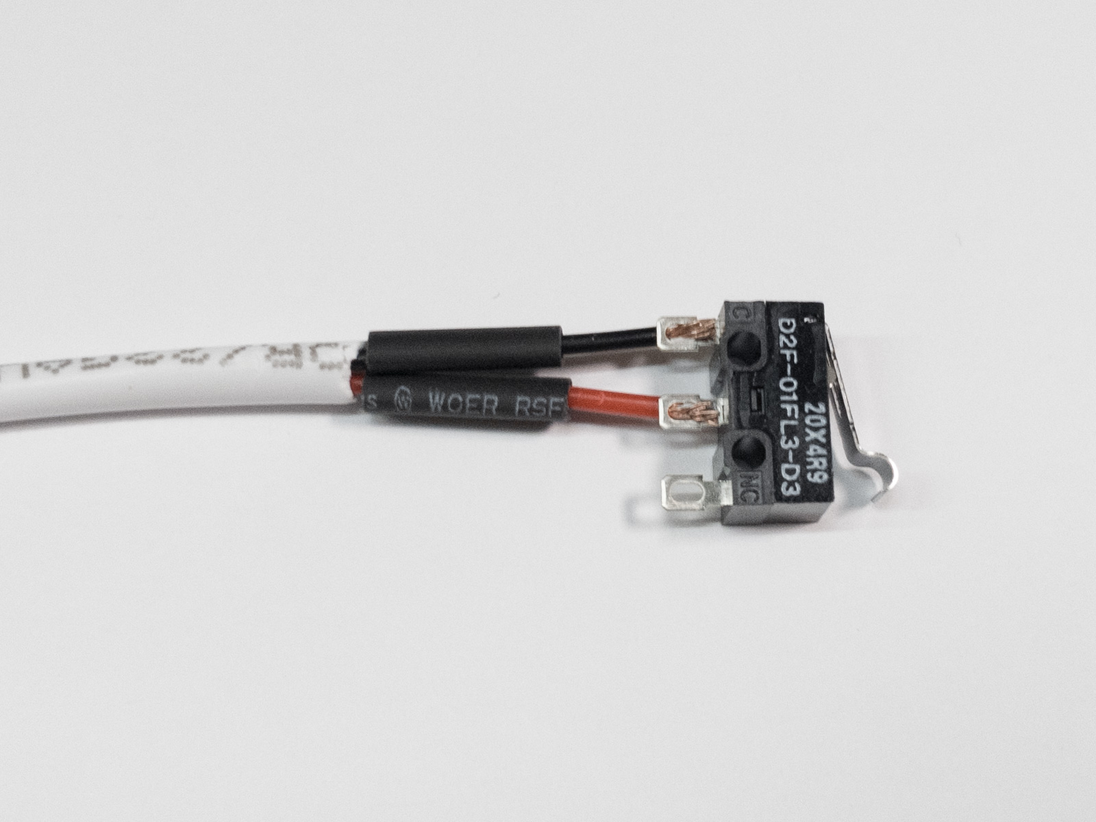
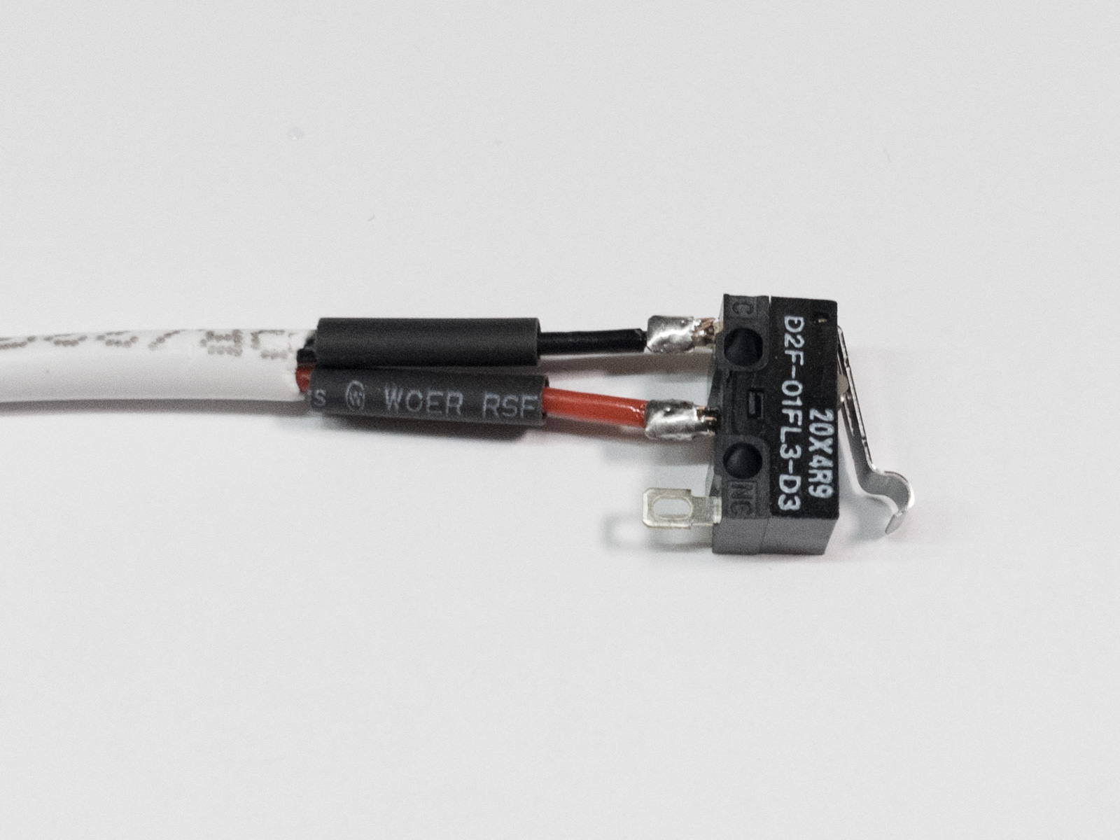
- We are using a NO (Normally-Open) connection so solder a wire to each of the two connectors nearest the switch hinge, as shown. Polarity doesn't matter as long as you use the middle pin and pin nearest the hinge.
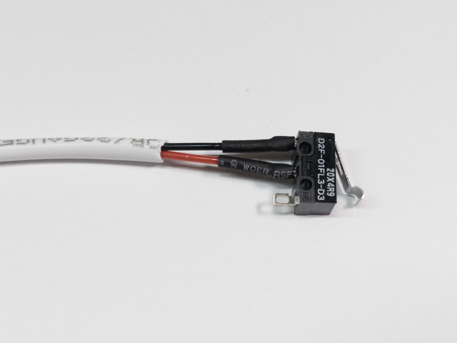
- Once both wires are soldered, slide the heat shrink over the solder joints and shrink the tube with a lighter or heat gun.
- Do this for both switches.
Attach the Switches
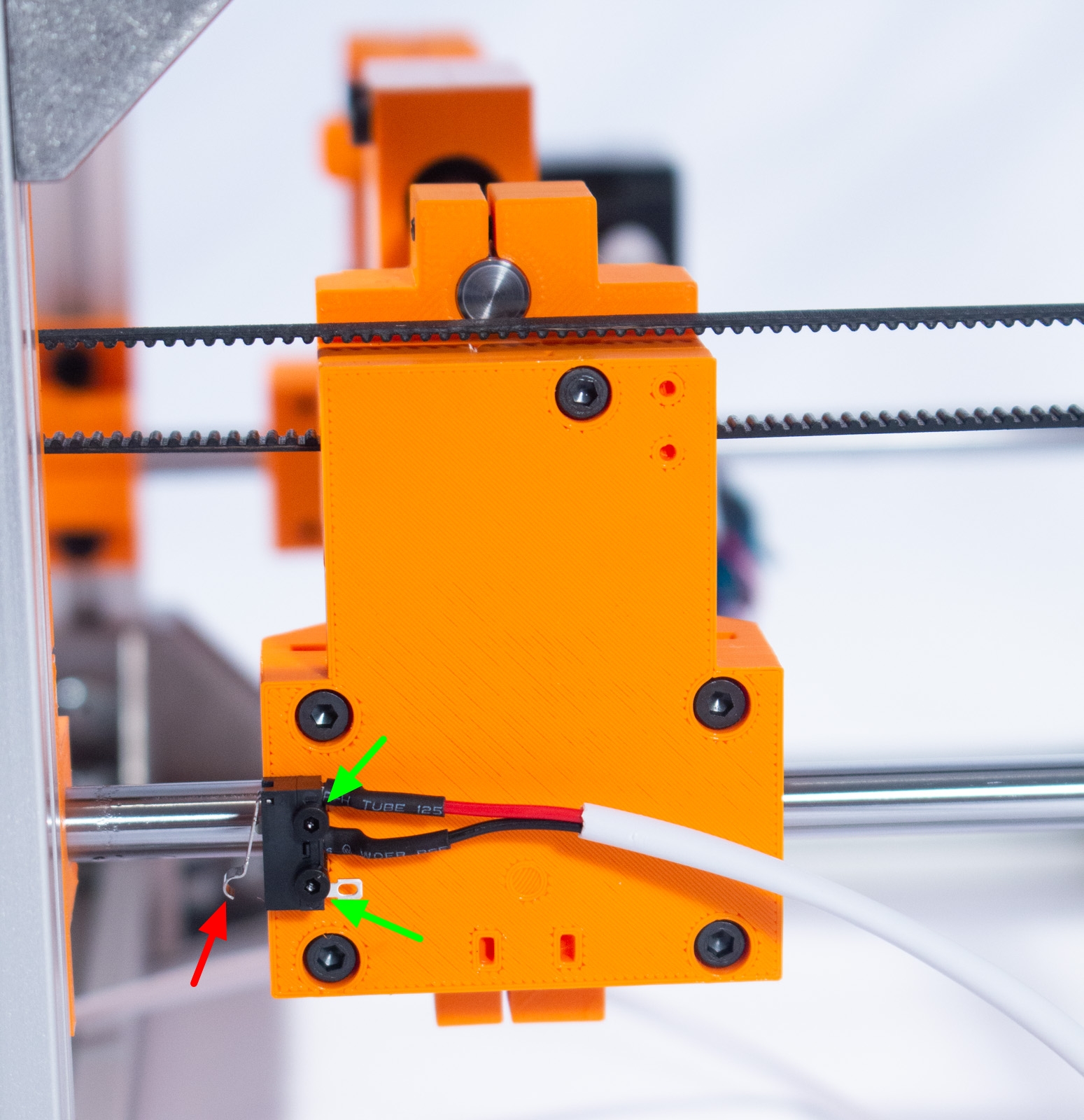

- Attach the Y-Axis limit switch as shown using two M2x8mm bolts. These bolts are just self-threaded into the plastic components so do not over-tighten!! Simply turn until you are unable to turn any longer with 2 fingers and make sure the switch is secure.
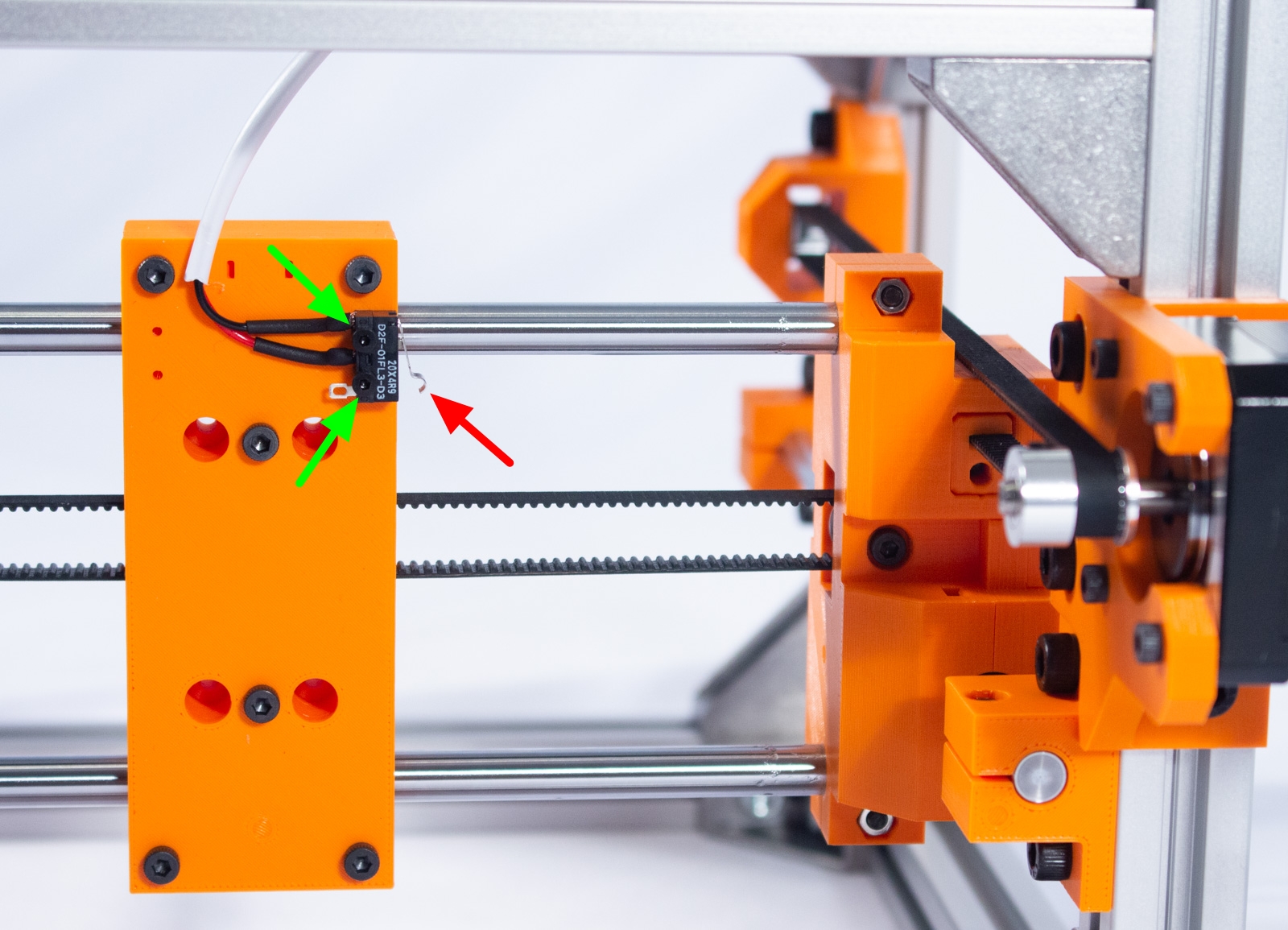
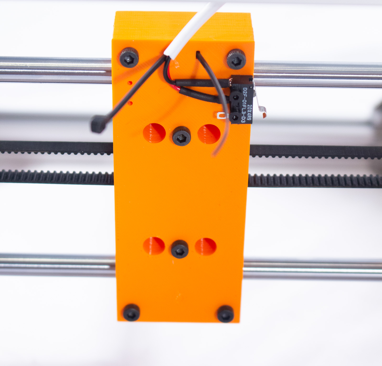
- Attach the X-Axis limit switch as shown using two M2x8mm bolts just as before.
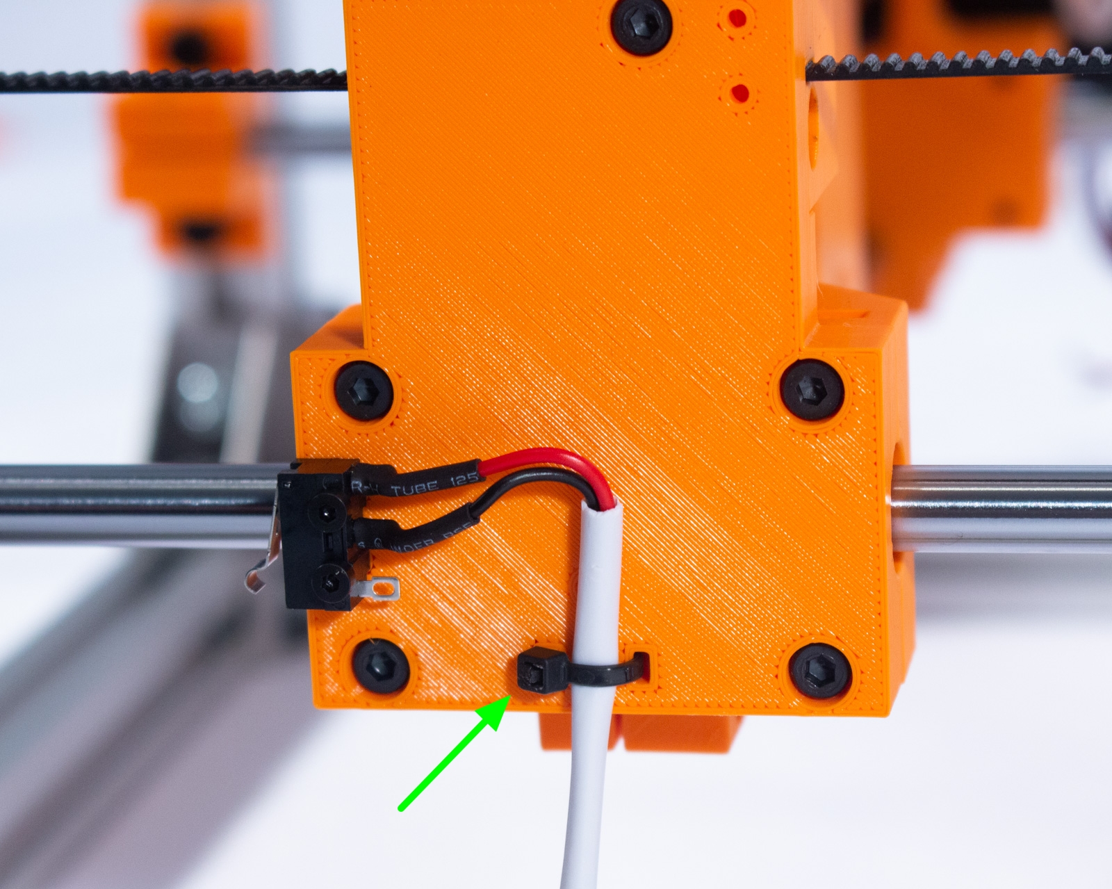
- For both switches, thread a zip tie through the provided channel and secure the cable as shown, with just a little slack between the zip tie and the switch.
- Snip the excess zip tie off.
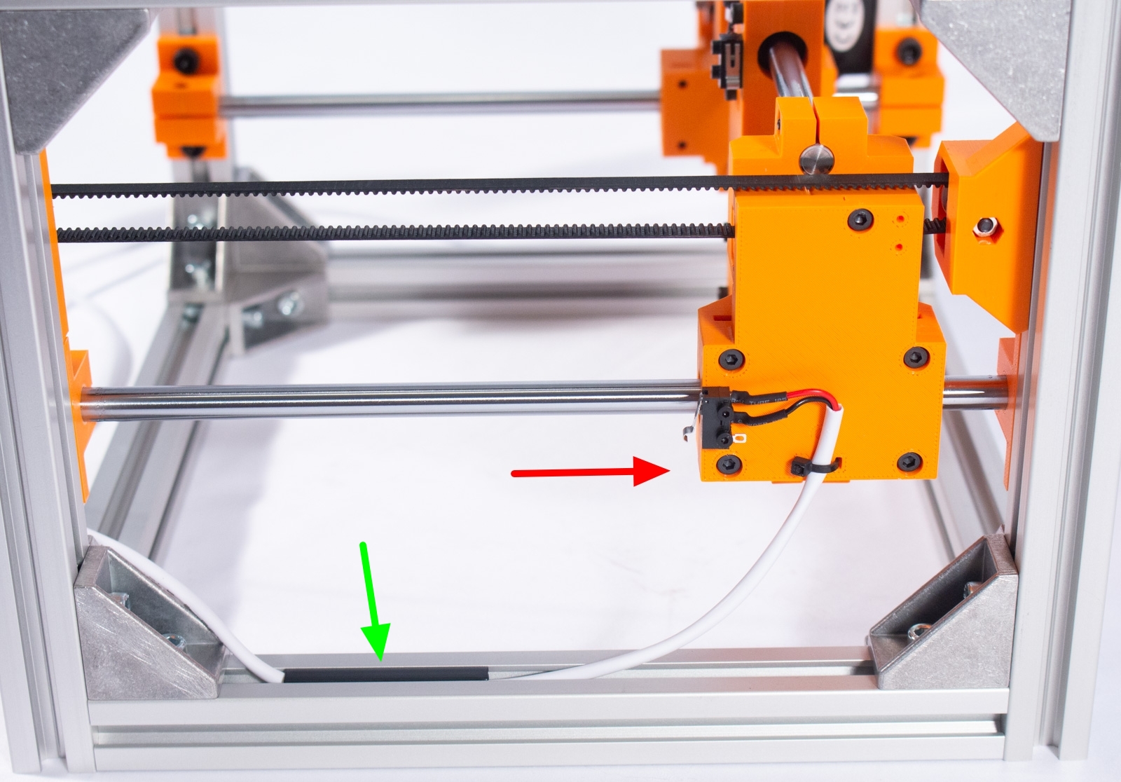
Run the Y-Axis Limit Switch Cable
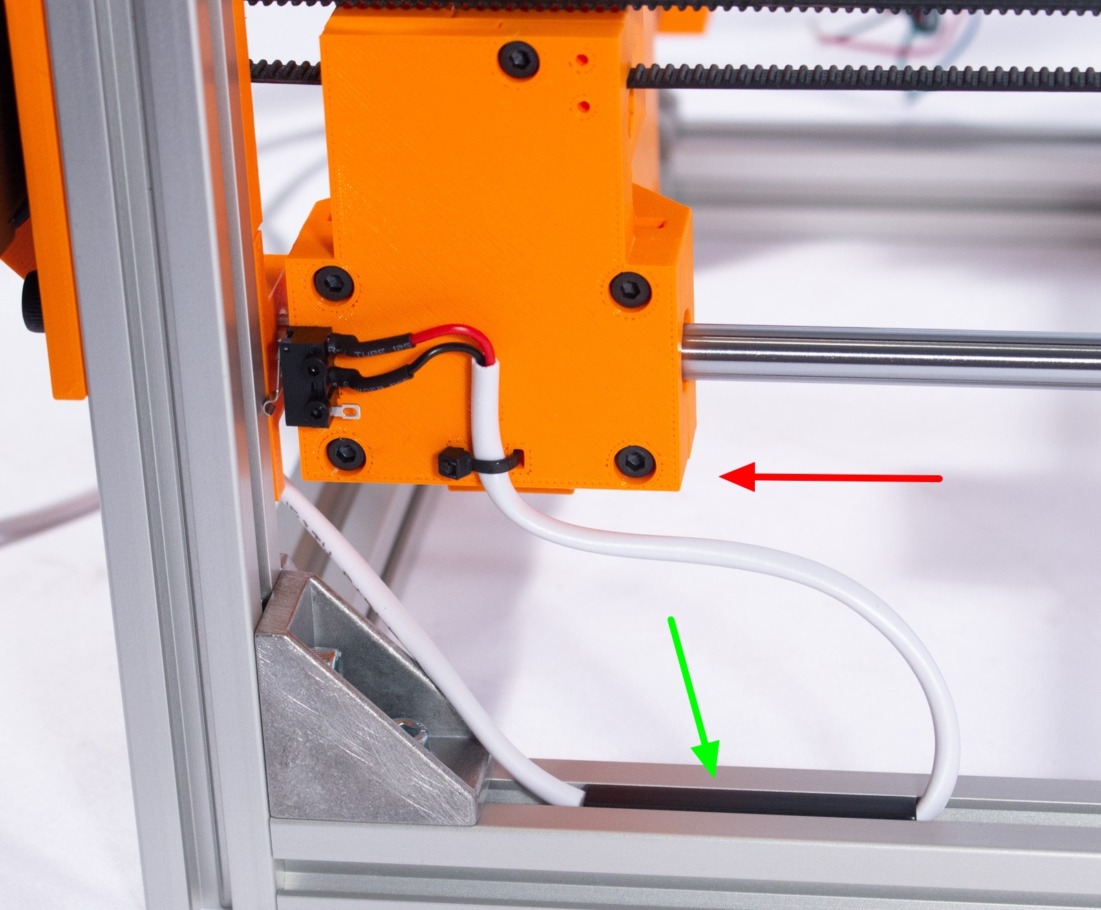
- Cut off 2 pieces of slot cover in 45mm and 60mm lengths using scissors.
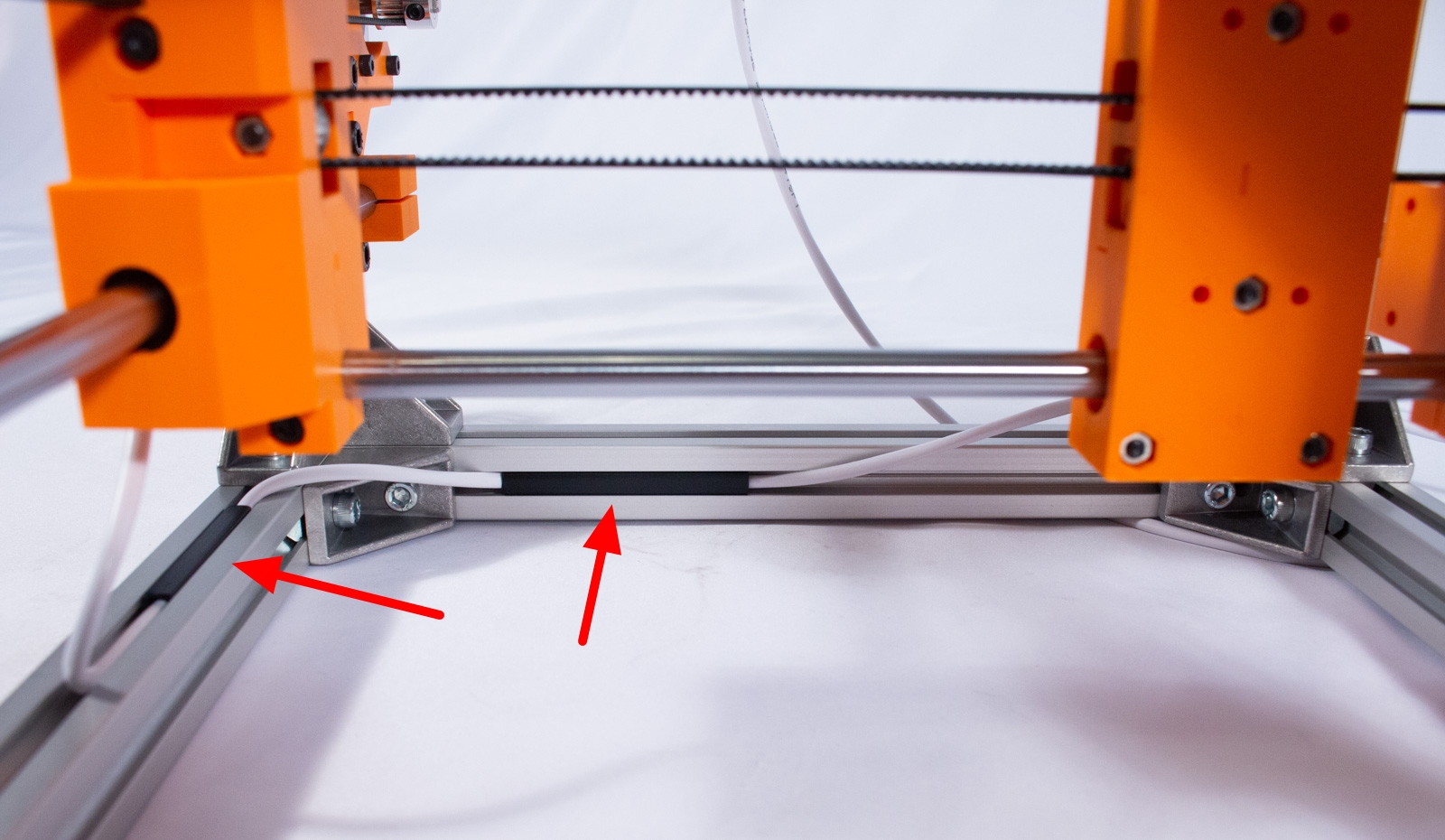
- For the Y-Axis switch, run the cable through the lower extrusion channel, as shown, and then press the 45mm slot cover over the cable. You want one end of the cover to be roughly in the middle of the extrusion.
- Move the Y-Axis back and forth and make sure there's just enough slack in the cable for unhindered motion.
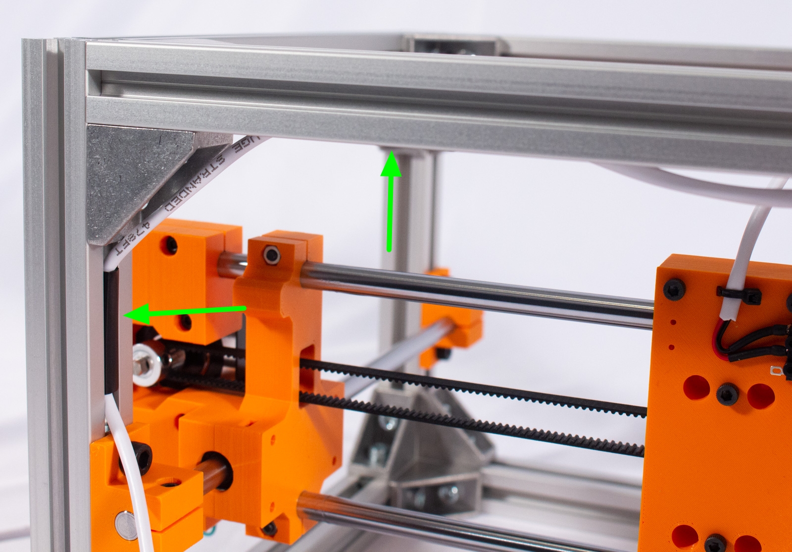
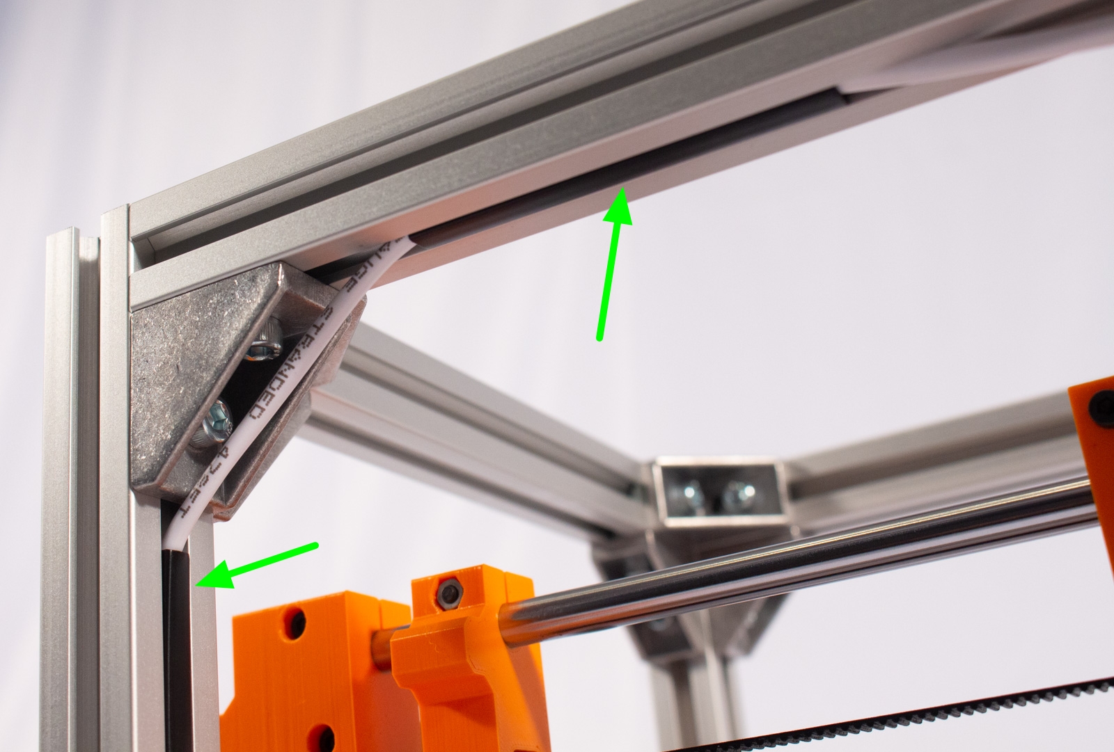
- Run the cable around the corner and into the front channel of the back-lower extrusion, as shown, then press the 60mm slot cover into the channel.
- Take the rest of the cable and run it out the back of the machine and leave it for now.
Run the X-Axis Limit Switch Cable
- Cut off 2 pieces of slot cover in 65mm and 30mm lengths using scissors.
- For the X-Axis switch, run the cable through the underside channel of the back-top extrusion, as shown, and press the 65mm slot cover over it into the channel. One end of the cover should be roughly in the middle of the extrusion.
- Move the Y and X axis around to all 4 corners to ensure that the cable has enough slack to reach the front but not so much that it gets bunched up when moving to the back.
- Now run the cable around the corner and into the inside face channel of the back-right upright extrusion, as shown. Press the 30mm slot cover over the cable.
- Take the rest of the cable and run it out the back of the machine and leave it for now.
Run Motor and Laser Cables
Components
warning The laser module you have may look different than the one shown here. This is ok as long as it has the correct mounting hole pattern. See the BOM guide for more.
While the Engravinator is capable of supporting a servo instead of a laser for use with a pen, that is not covered here. Please checkout the PenLift Mod for more info.
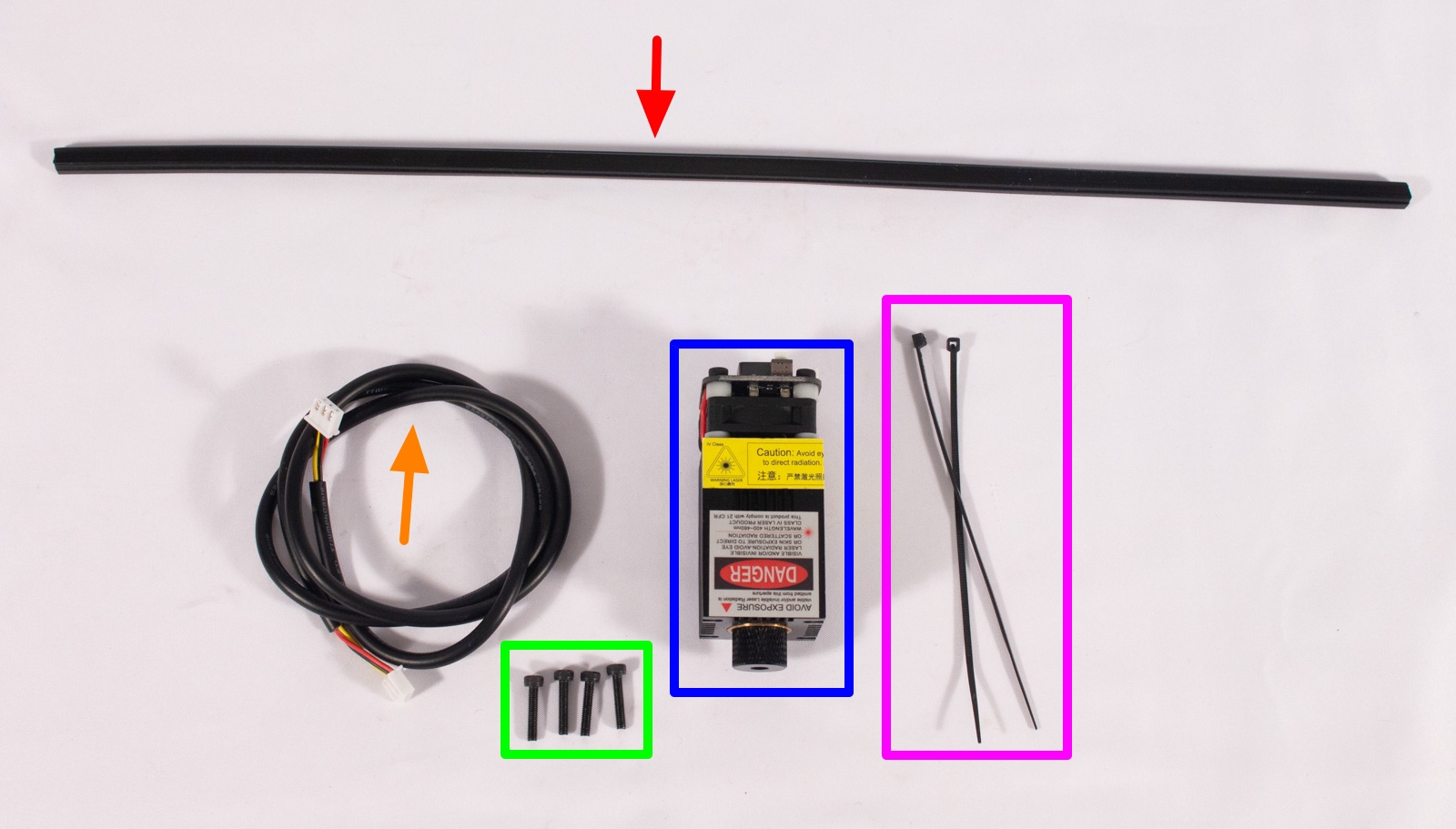
- Laser and associated cable
- M3x14mm bolt (x4)
- Zip ties
- Slot Cover
Motor Cables

- Cut 3 pieces of slot cover in 60mm, 40mm, and 40mm lengths using scissors.
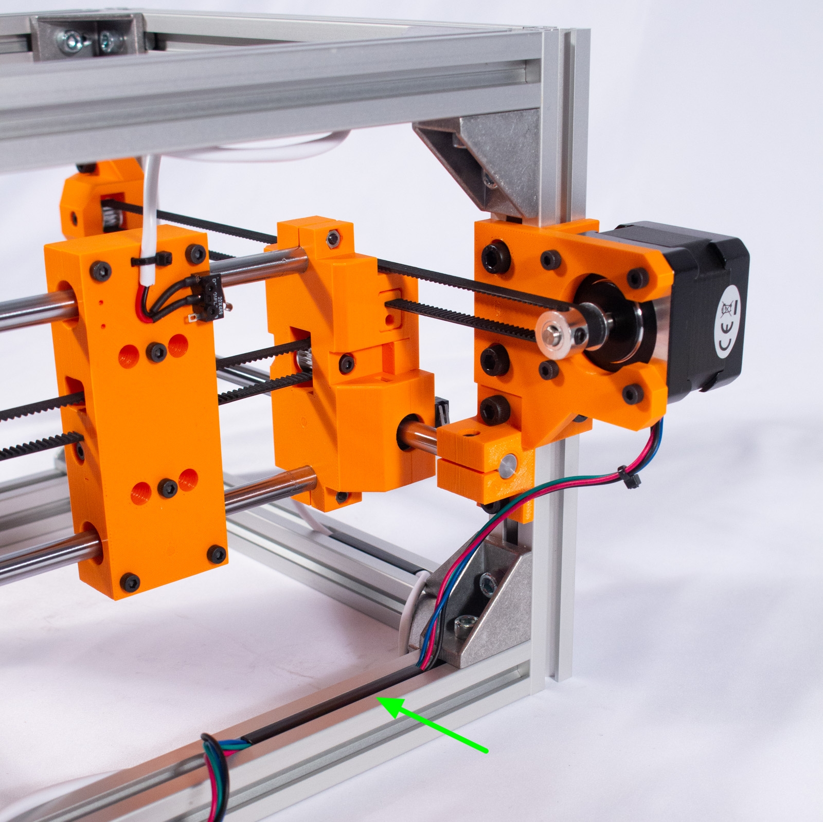
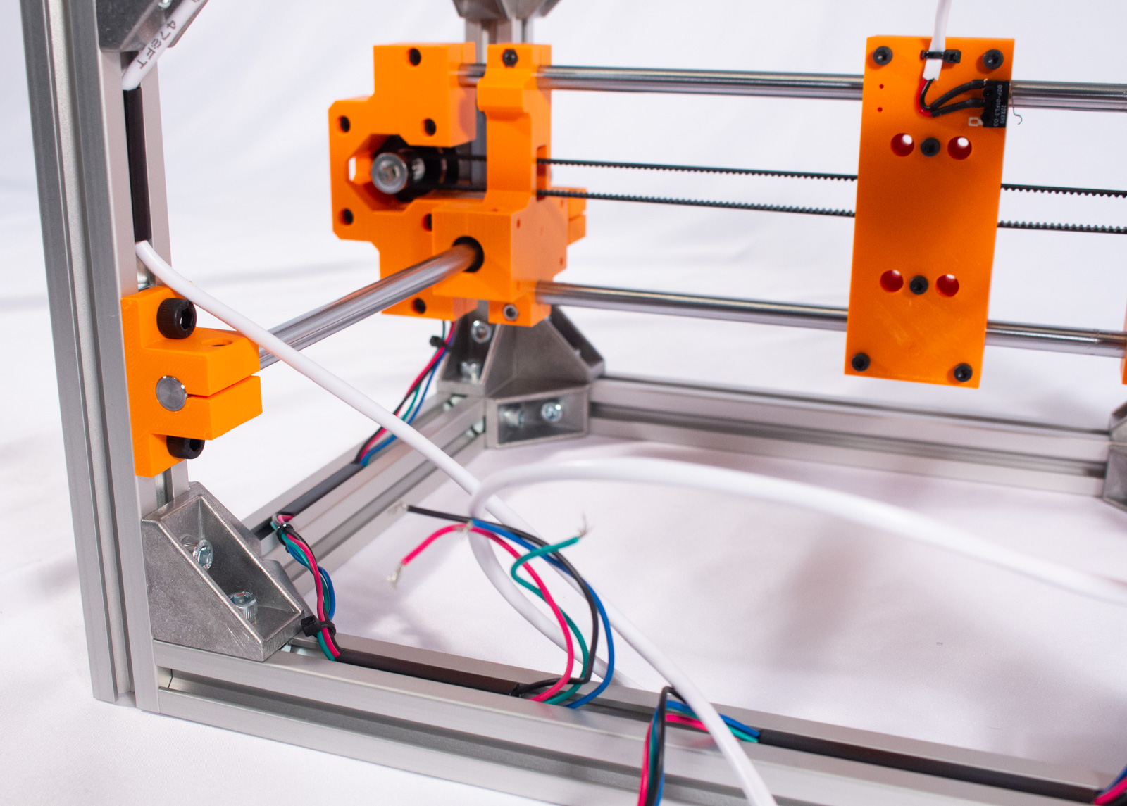
- Run the Y motor cable into the top channel of the back-lower extrusion, as shown, and press the 60mm cover over it.
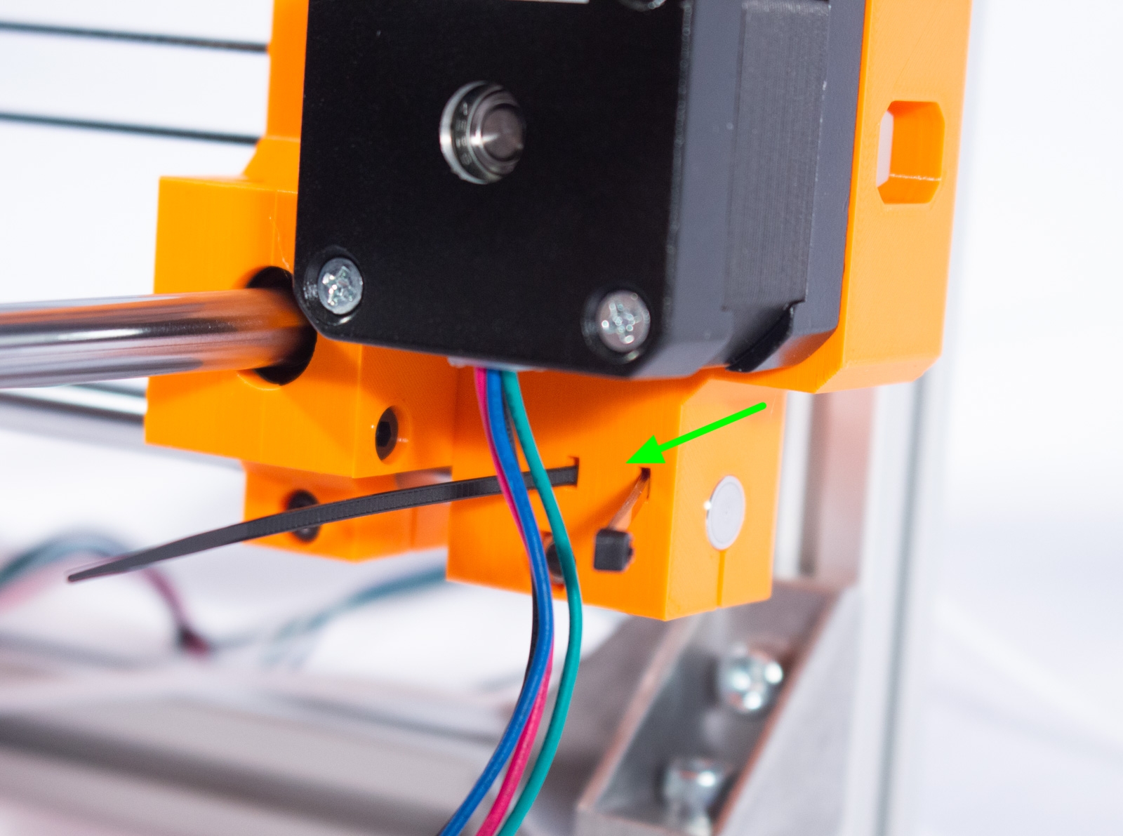
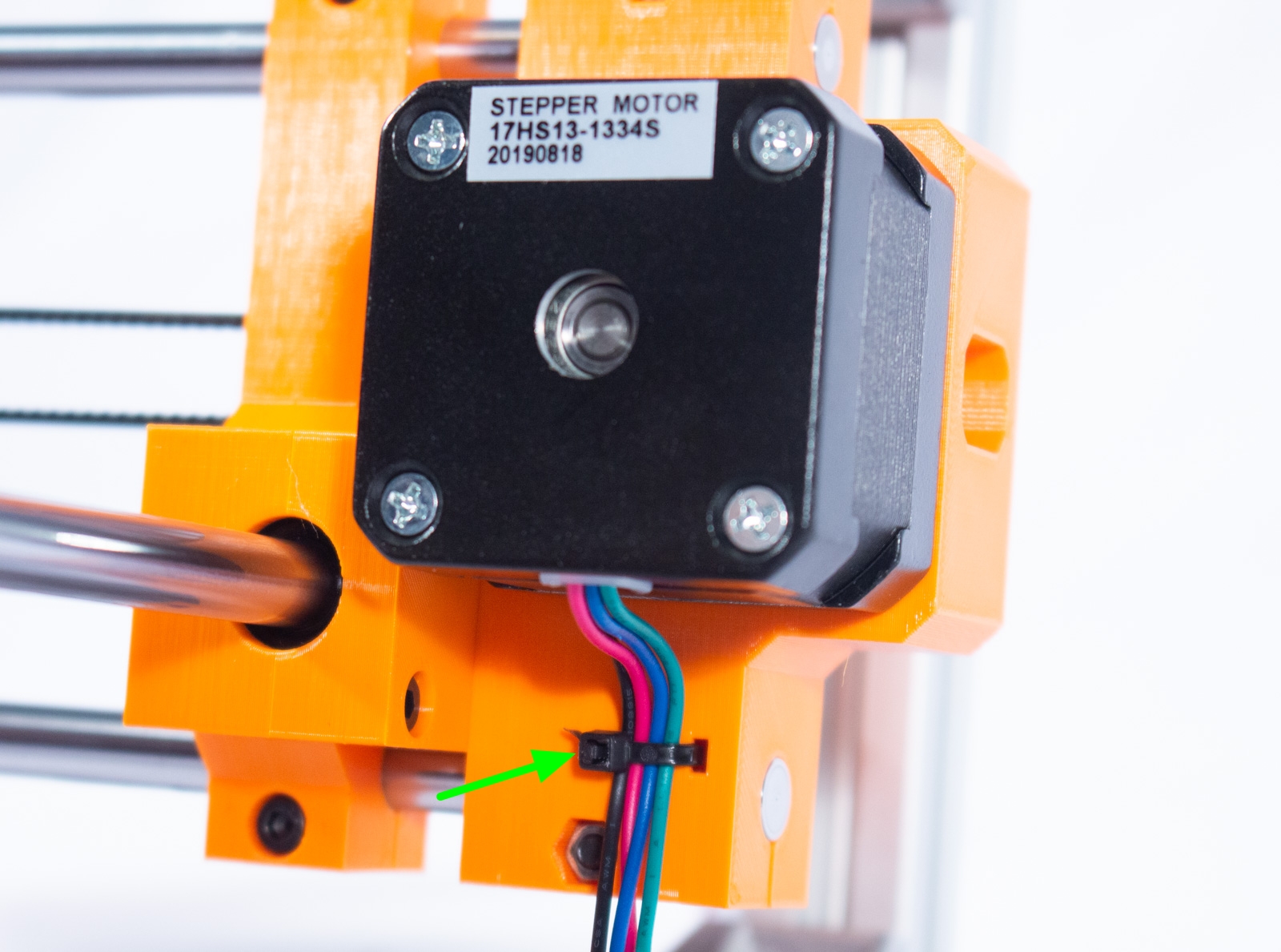
- Secure the X motor cables to the X motor mount using a zip tie, as shown.
- Run the X motor cable into the top channel of the right-lower extrusion and press the 40mm cover over it, with one end of the cover in roughly the middle of the extrusion.
- As with the Y-Axis limit switch cable, ensure that there's just enough slack to move the Y-Axis back and forth.
- If your motor has 4 unbound wires, it is recommended to use 2-3 zip ties to bind the wires between the slot cover and the motor. Snip off the excess zip tie.
- Run the rest of the X motor cable into the top channel of the back-lower extrusion, as shown, and cover with the 40mm slot cover.
Mount Laser and Run Cable
warning The Engravinator can support a variety of laser modules. This step assumes that your laser module came with its own cable. Therefore what is shown here is merely an example and yours may look different.
- Cut a 65mm piece of slot cover using scissors.
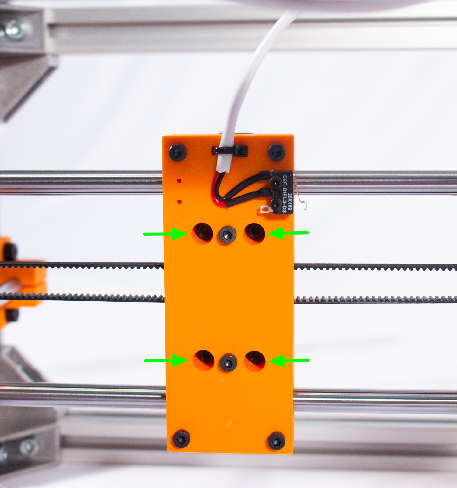
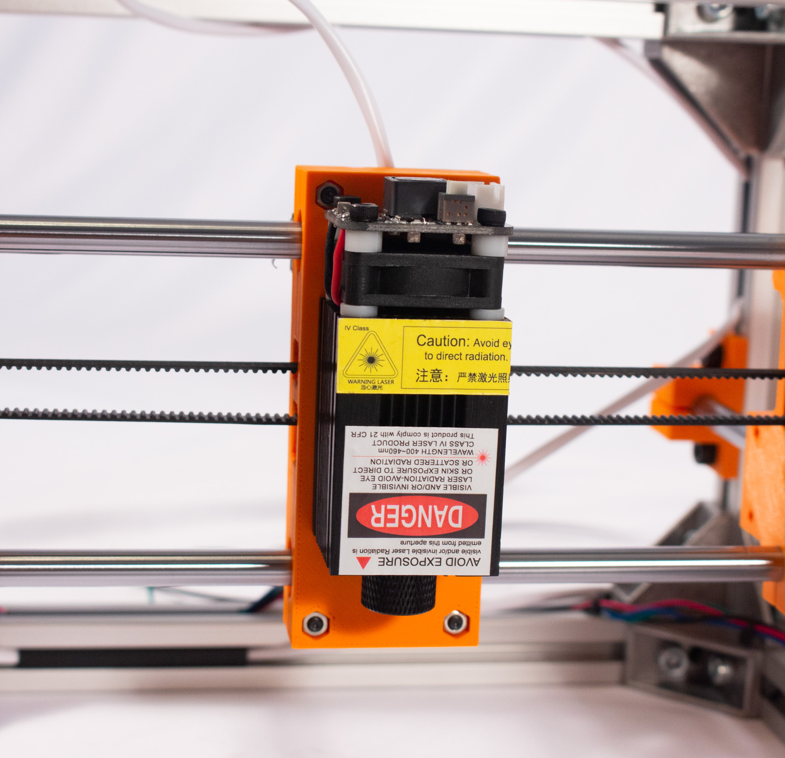
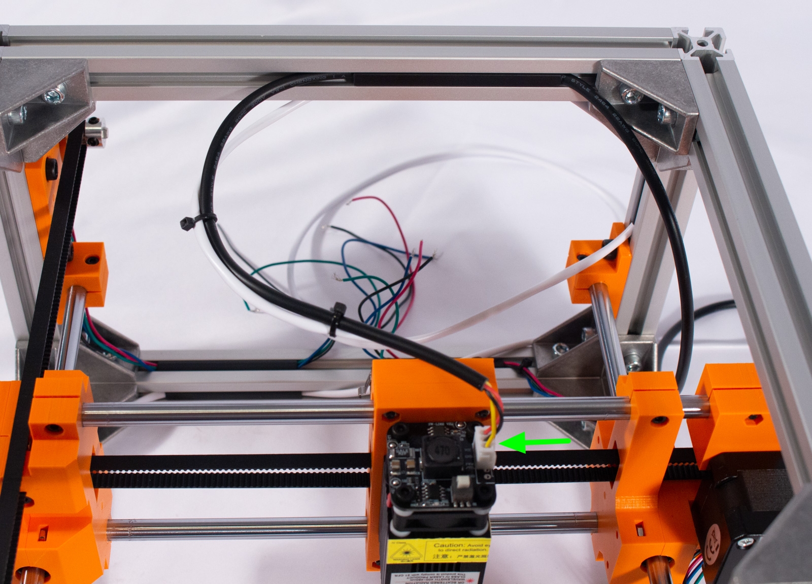
- Install your laser or pen mechanism as shown, using the 4 M3x14mm bolts through the back of the X-Axis carriage.
- Connect the cable that came with your device of choice.
- Move the X-Axis carriage to the front-right of the machine.
- Zip tie the cable to the existing limit switch cable in 2-3 places.
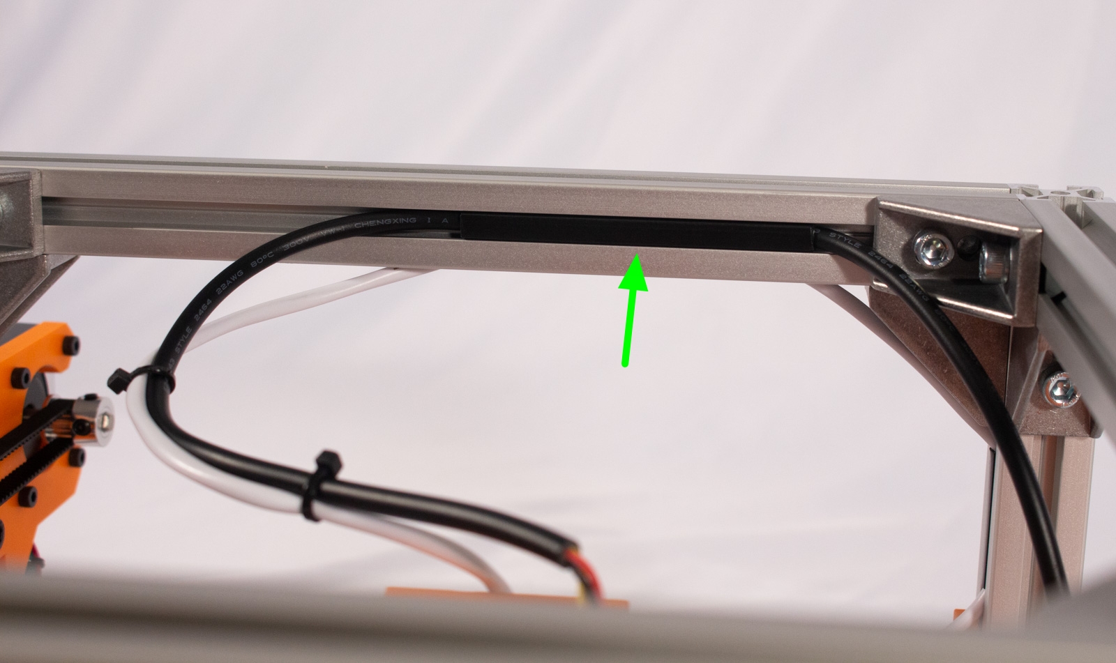
- Take the cable and run it through the front channel of the back-top extrusion, as shown. Press the slot cover over it.
- Move the device around to all corners and make sure there's just enough slack.
Oh man, it's looking good! If it only had a brain...