Controller
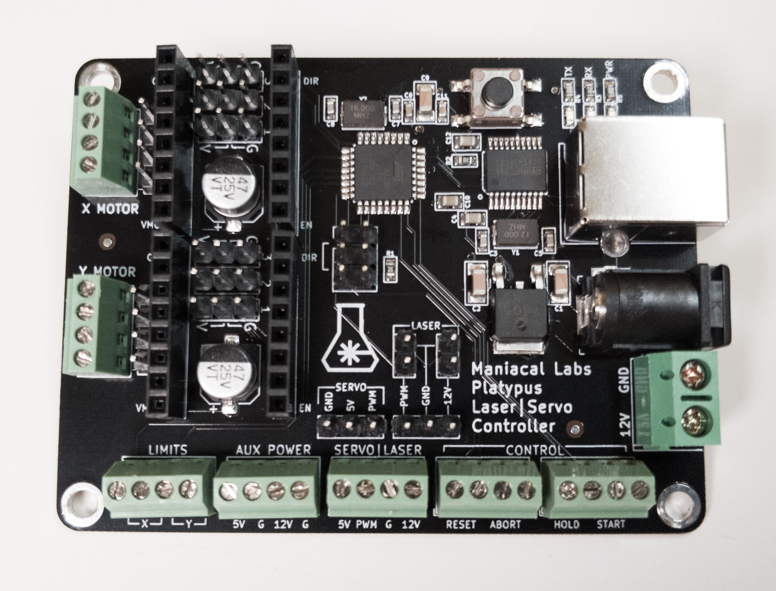
The Engravinator is a flexible platform that is capable of using a wide variety of controller boards. It you bought the kit version, it likely came with the Platypus controller so that's what we will show here. It was designed specifically with the Engravinator in mind and simplifies the process as much as possible. Installing another controller will likely be very similar.
This section assumes that you already have a fully assembled controller board with stepper drivers installed and configured correctly. If you are using the Platypus please refer to its documentation for correct assembly and setup. If using another controller please refer to its documentation.
From here on you may notice a green, instead of black, controller board in a few pictures. The main assembly guide pictures were taken before the final Platypus board was complete. Anything important shows the correct, newer, board.
Tools Required

- 2.5mm Hex Key for M3 bolts
- call_split Hex Key for M5 bolts
- 3mm for the kit version
- 4mm for the BOM version
- Wire strippers
- Wire snips
Controller Base Plate
Components
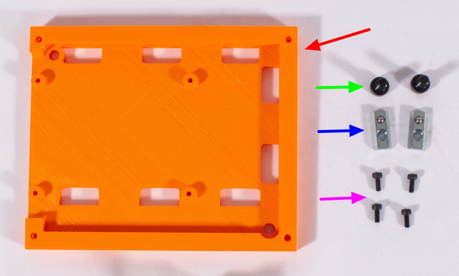
- BasePlate_Platypus (x1)
- M5x10mm bolt (x2)
- Post Assembly Spring Nut (x2)
- M3x5mm bolt (x4)
- Platypus Controller Board
Mount Base Plate
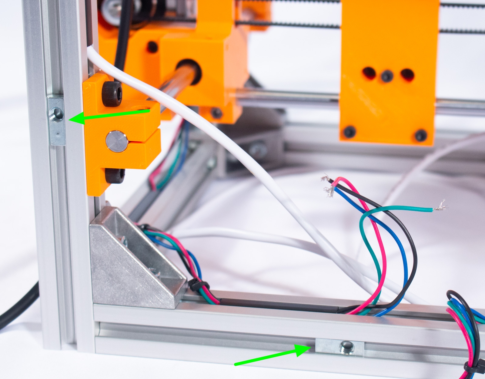
- Insert the 2 spring nuts as shown
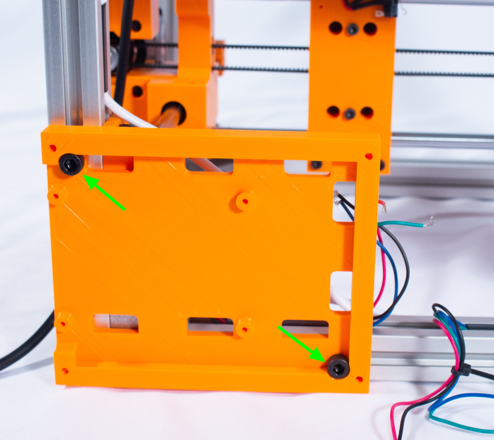
- Place M5 bolts through the holes in the base plate and use them to better align the spring nuts. The base plate should be flush with the side and bottom.
- Tighten the bolts.
Mount Controller
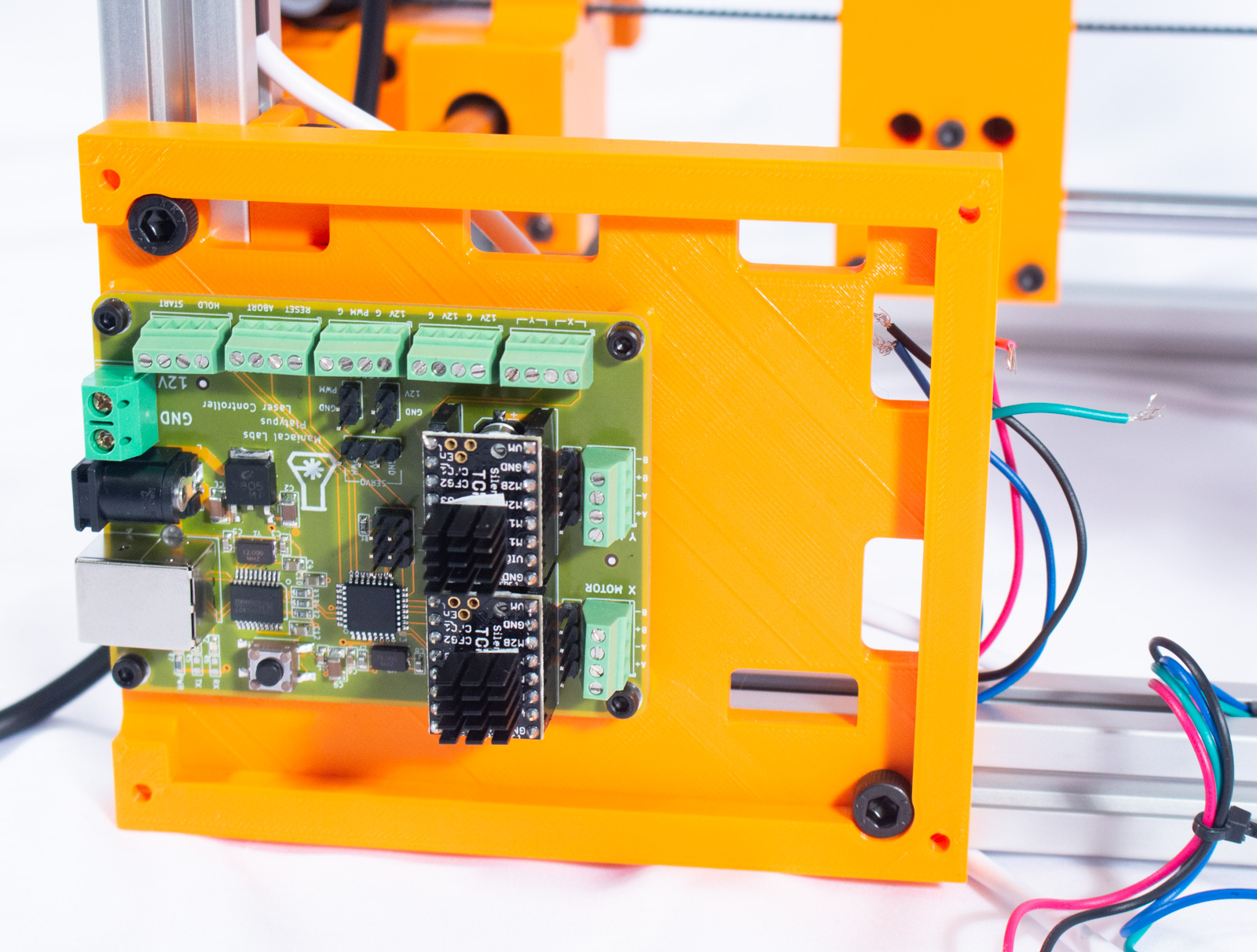
- Using the 4 M3x5mm bolts, mount the controller to the base plate as shown. As the bolts are threaded directly into the plastic do not overtighten them. As tight as you can get them with 2 fingers is fine.
- Be sure that the USB and Power ports are facing out to the left (while looking at the back).
Controller Wiring
Motors


warningcall_split READ THIS WHOLE SECTION CAREFULLY! (You're reading all sections carefully, right?)
Between the kit version and BOM version the motors are slightly different. While hooking up the motor wrong won't necessarily destroy anything, wouldn't you rather get it right the first time?
- Run the X motor cable through the lower right hole on the base plate.
- call_split Prepare and connect motor wires:
- If using the BOM version motor without a terminating connector:
- Pull the wires towards the X motor terminal on the controller to determine the total length you need. You may trim off any excess, making sure to leave enough to comfortably reach the terminal. If you do, be sure to strip ~3mm of insulation from the end of each wire.
- Using the screw terminals connect the wires as follows:
- A+ → Blue
- A- → Red
- B+ → Green
- B- → Black
- Now run the Y motor cable - DO NOT cut the cable! - through the same base plate hole and repeat the steps above, except use the follow wire order:
- A+ → Black
- A- → Green
- B+ → Red
- B- → Blue
- If using the kit version motor with a female connector:
- The cables are much longer than required but using the connector is convenient. Feel free to bundle up and zip tie the wires. If you would like slightly neater wires however, follow the wire preparation directions from the "without connector" section above.
- Using the male header connect the wires as follows:
- A+ → Black
- A- → Green
- B+ → Blue
- B- → Red
- Now run the Y motor cable - DO NOT cut the cable! - through the same base plate hole and repeat the steps above, except use the follow wire order:
- A+ → Red
- A- → Blue
- B+ → Green
- B- → Black
- If using the BOM version motor without a terminating connector:
Limit Switches

- Run the X limit switch cable through the top-right hole in the base plate.
- Strip ~3mm of insulation from the ends of the wires (if not already) and connect it to the Limit terminal where it's marked X. Polarity doesn't matter.
- Run the Y limit switch cable through the same hole and repeat the same connection process, but where it's marked Y.
Laser / Servo Connection

Below are the most likely we've seen for cable colorings. But these might be wrong depending on your specific device. BE SURE to check the pinout labels on your laser module and match the colors up correctly on the controller side!!! These may not be correct!
- Run your cable through the top-middle base plate hole.
- If your laser cable came with a cable that terminates in dual 2-pin connectors:
- Red is 12V
- Black is Ground
- Yellow is PWM
- If your laser cable terminates in a single 3-pin connector:
- Red is 12V
- Black is Ground
- Yellow is PWM
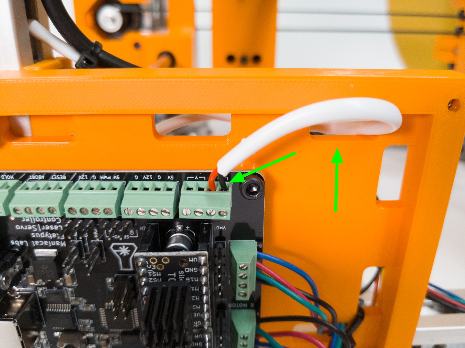
- If you are using a servo, use the servo connector shown. NOTE!! The servo uses 5V instead of 12V. If you connect to the headers marked for the laser you will blow up your servo!
- Black is Ground
- Red is 5V
- Orange is PWM/Signal
- The Platypus has discrete male headers for each of the above listed options. But it is honestly easier to use the
Servo|Laserscrew terminal and follow the color coding listed above to connect each wire to the right spot. We like screw terminals so this is what we've shown above. If you have 2 black/ground wires, just insert them into the same terminal slot.
Hooray, you're nearly there! Don't worry about putting the controller cover on at this point. Let's do some pre-flight checks in the next section.
Also, if you have the enclosure, we will install that after the pre-flight checks.