Pre-Flight Checks
You are nearly there! But there's a few things that need be setup correctly before you can continue. As noted before, we are assuming you are using the Maniacal Labs Platypus controller, which uses grbl. If you are using a different controller with a different type of firmware you can still find this section useful but will need to translate to the controller of your choice.
Control Software
We've held off on this part until now but it's pretty important... you need software to control the Engravinator. Since it runs grbl you've got plenty of options, including but not limited to:
This guide will not go into how to do many of the things described below with the software you choose to use, as it's entirely dependent on your choice. Please see the appropriate documentation for your software if you are unsure.
For use with the Platypus controller we have provided basic setup instructions for a few of the software options in the Platypus Software Documentation.
Stepper Driver MicroStepping
You will need your stepper drivers disconnected from the controller for this step.
This guide assumes you are using 1/16 microstepping on your stepper drivers. For the recommended TCM2100 drivers that requires setting CFG1 to Ground and leaving the others open. On the Platypus this can be done with a jumper and looks like this:
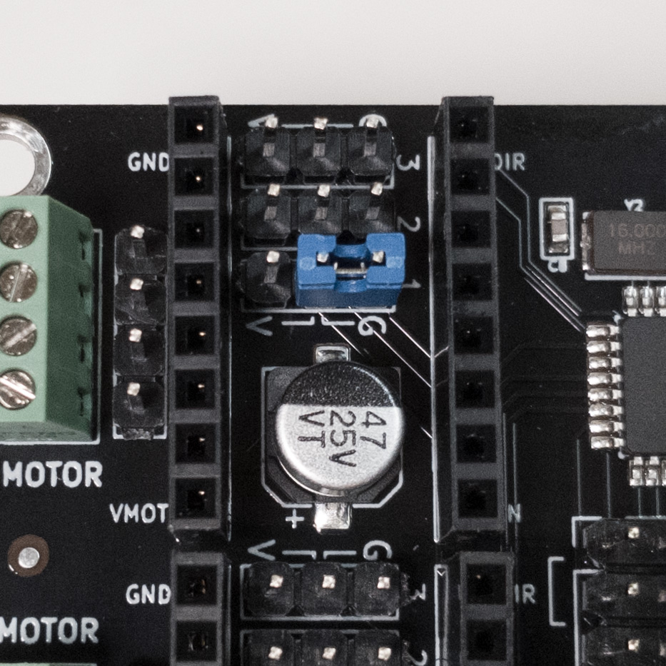
If you are, however, using other stepper drivers, please see the documentation for your particular driver and controller.
Stepper Driver Current Control
You may now insert your stepper drivers into the sockets. Make sure the pins line up with the GND, VMOT, DIR, and EN labels. Note that for TMC drivers, they should be "upside-down" with the driver IC facing the controller.
The stepper motors specified in the BOM have a peak current per-phase of 1.3A but we recommend, for the sake of lifetime and heat, to run them at a max of 1.0A. For the recommended TCM2100 drivers you must set the vRef trimpot to 1.0V. You will need a digital multi-meter to do this.
The easiest way is using meter leads with alligator clips and a small flat-head screw driver. Connect the red (positive) clip to the shaft of the screwdriver (contacting the metal) and the black (negative) clip to a ground pin on the controller. We recommend using a small length of wire in a screw terminal for this and then connect the clip to that.
Now power up the controller and use the screw driver to turn the trim-pot until your multi-meter reads 1.0V
If you want to know more about setting the current limiting on "StepStick" style motor drivers there are many online resources. Just search for <your driver name> set current limit.
Power Up and USB
Before we can do anything else you will need to get connected to your computer and power.
First, use a 12V/10A power supply (or similar as listed in the BOM guide) to power up the controller and your Engravinator. You may hear a slight buzz from the motors but nothing should move!
Now, use a USB-B to USB-A cable to connect the Platypus controller to your computer. Most modern operating systems should recognize the serial device immediately, if not please see the controller's documentation for more info on drivers.
Now, in your control software connect to the Engravinator controller as a serial device.
If you can access the serial console in your software you should see something like:
Grbl 1.1h ['$' for help]
Controller Configuration
If you are using another controller with a clean grbl setup you will need to apply some config changes. The following must be entered in the serial console or via any machine settings UI provided (LightBurn and OpenBuilds Control both have this). If entering into the console, just copy the line (such as $22=1) into the console and hit enter. You should receive ok in response. The lines beginning with ; are just comments and don't need to be entered into the console. However, all of the config change commands must be entered in the order shown here!
;Step idle delay, ms;
$1=255
;Step port invert, mask;
$2=0
;Direction port invert, mask;
$3=0
;Step enable invert, boolean;
$4=0
;Limit pins invert, boolean;
$5=0
;Status report, mask;
$10=0
;Junction deviation, mm;
$11=0.010
;Arc tolerance, mm;
$12=0.002
;Report inches, boolean;
$13=0
;Soft limits, boolean;
$20=1
;Hard limits, boolean;
$21=1
;Homing dir invert, mask;
$23=1
;Homing feed, mm/min;
$24=100.000
;Homing seek, mm/min;
$25=750.000
;Homing debounce, milliseconds;
$26=250
;Homing pull-off, mm;
$27=1.000
;Max spindle speed, RPM;
$30=1000
;Min spindle speed, RPM;
$31=0
;Laser mode, boolean;
$32=1
;X steps/mm;
$100=100.000
;Y steps/mm;
$101=100.000
;X Max rate;
$110=9000.000
;Y Max rate;
$111=5000.000
;X Acceleration;
$120=1500.000
;Y Acceleration;
$121=1000.000
;X Max travel, mm;
$130=130.000
;Y Max travel, mm;
$131=130.000
;Homing cycle, boolean;
$22=1
Triple check that you got all of these correct! You need all of them! Please note that these include basic speed settings that we've found work well. If you are adventurous you can try faster or slower, depending on your needs.
If you are not using 1/16 microstepping on your motor drivers you will need to use different values for the steps/mm options. We recommend using this calculator. Just note that you will be using GT2 (2.0mm pitch) belts with 1.8° motors, and 16 tooth pulleys.
First Move
With all that ready, let's get moving!
For this part, just in case you did something wrong, be ready to pull the power. Now hit the homing button in your control software or enter $H in the serial console.
The X-axis should move to the left and touch off the limit switch twice. Then the Y axis should move towards the back and touch off twice as well.
If either of the axis moved in a different direction you simply wired the motor backwards. The easiest way to fix this is to just flip the wires for that axis 180° on the connector. Though you can also flip the direction mask in the grbl config.
Setting the Home Offset
Grbl expects to home in the back-left corner but it also wants that to be 0,0 as that's what most CNC machines use, with negative coordinates for the Y axis. But most laser control software doesn't play nice with this. Instead we want to tell grbl that the homing location is actually 0,130 (note we set the max travel limits to 130mm above).
Simply go to the serial console and enter this command:
G10 L2 P1 X0 Y-130
That only needs to be done once and will be saved in EEPROM across reboots of the controller. Now back-left will be 0,130 and front-left will be 0,0
That's It
You should now be able to jog around and since we enabled both hard and soft limits nothing should crash.
Because using lasers without eye protection is a bad idea, let's move onto the next section and install the enclosure.
You may reconnect the laser cable now.
Controller Cover
Note: If you are installing the acrylic enclosure (which you should if you like your eyes!!) you can come back to this step after you have completed the enclosure and wired in the fan.
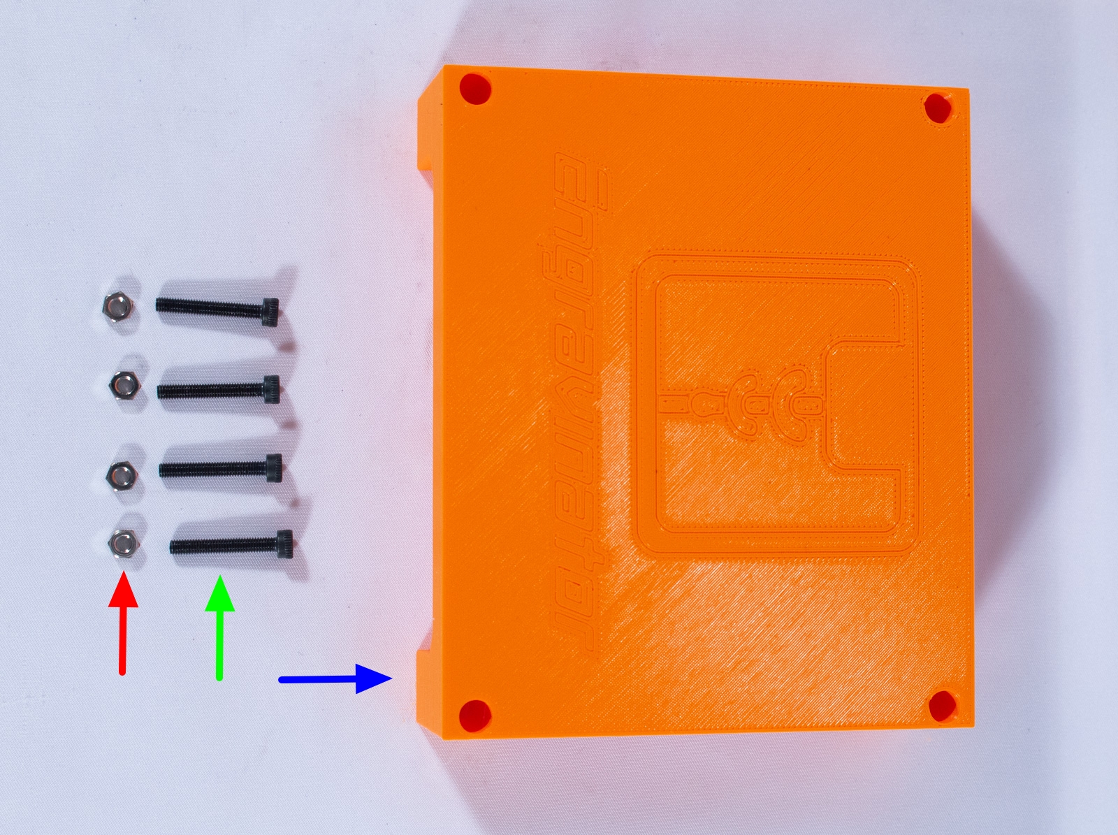
Components
- ControllerCover (x1)
- M3x20 bolt (x4)
- M3 nut (x4)
Assembly
- Flip the Engravinator up onto its front face.
- Insert an M3 nut into each of the slots on the controller base plate.
- Insert an M3x30 bolt into each of the holes in the cover and align with the holes in the base plate.
- Tighten all 4 bolts to secure the cover.
Now, since you love your eyes, let's move onto the enclosure! If you hate your eyes you can skip right to the last section.