Enclosure
Lasers can be dangerous and you've only got so many eyes!
We highly recommend installing this enclosure. If, for some reason, you hate your eyes then you can skip this section but Maniacal Labs takes no responsibility for lost vision. Seriously though, if you don't use an enclosure you MUST wear safety glasses at all times!
Tools Required
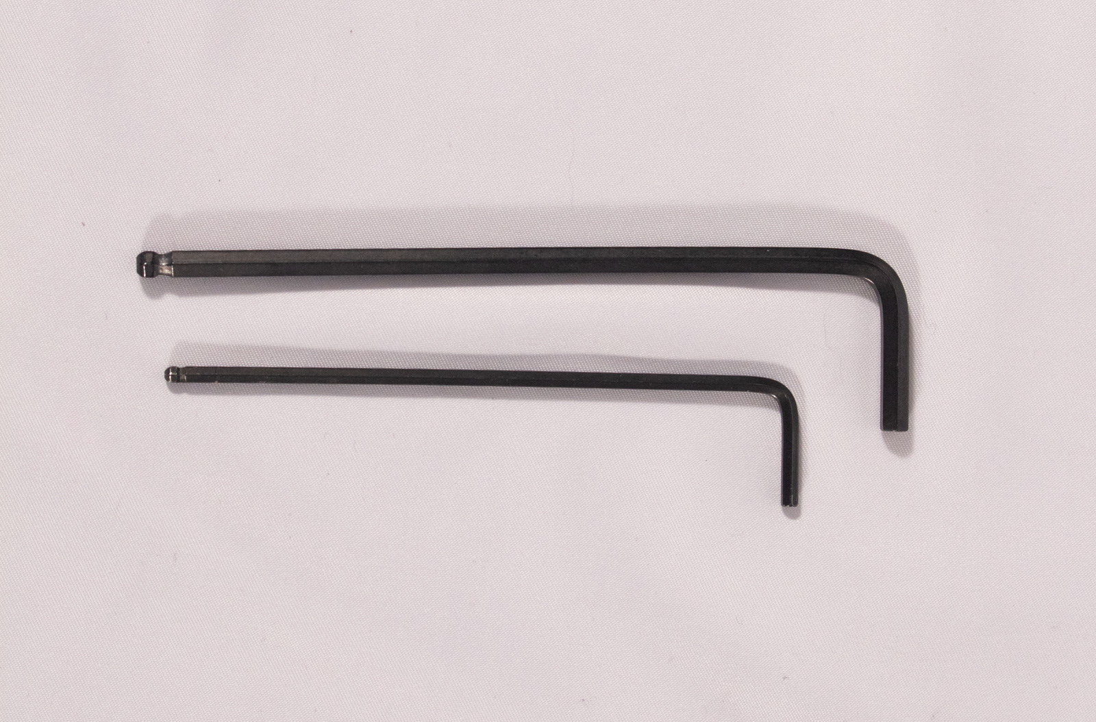
- call_split Hex Key for M5 bolts
- 3mm for the kit version
- 4mm for the BOM version
- 2.5mm hex key for M3 bolts
Side Panels
Components

- LeftPanel (x1)
- RightPanel (x1)
- x4_ExtensionBracket (x4)
- M5x10mm bolt (x4)
- M5x8mm bolt (x4)
- Post Assembly Spring Nut (x8)
- M3 nut (x4)
- M3x10mm bolt (x4)
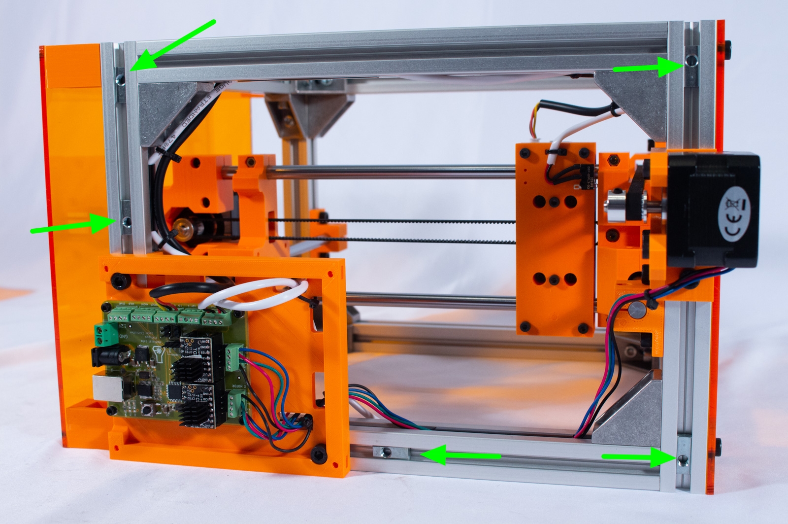
Left Panel
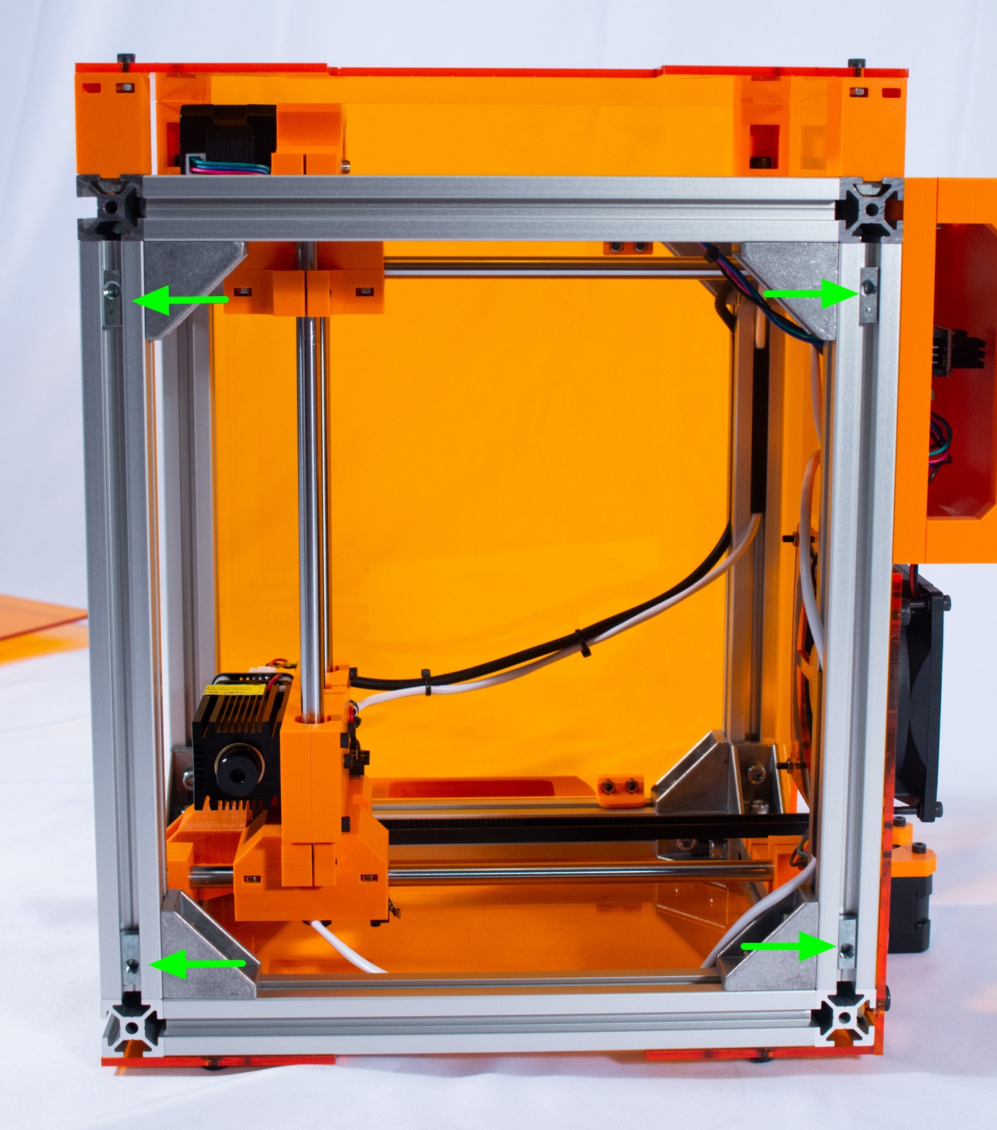
- Insert 4 of the spring nuts, as shown, into the extrusion channels on the left side.
- Remove the paper backing from both sides of LeftPanel.
- Mount the panel to the side using 4 of the M5x8mm bolts (the shorter ones!).
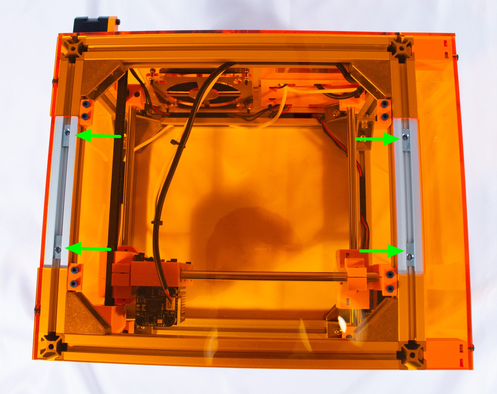
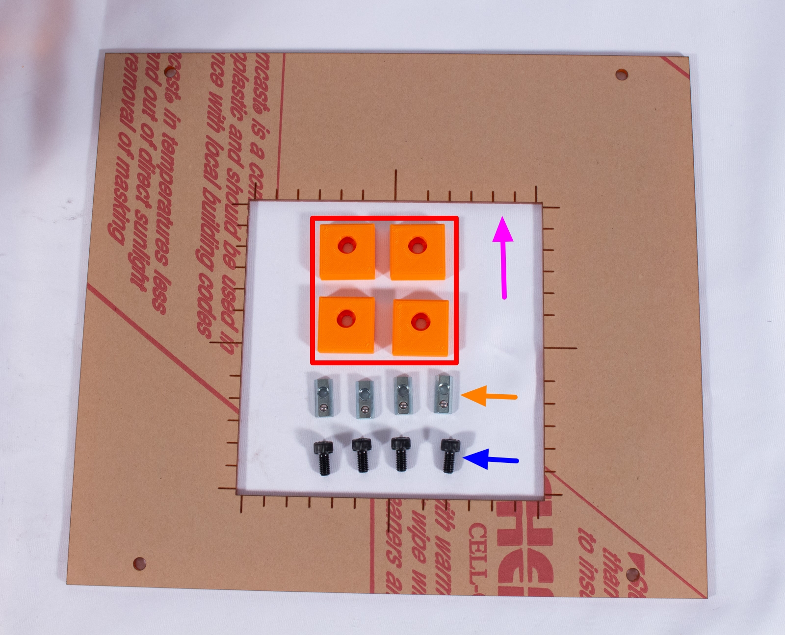
Extension Brackets
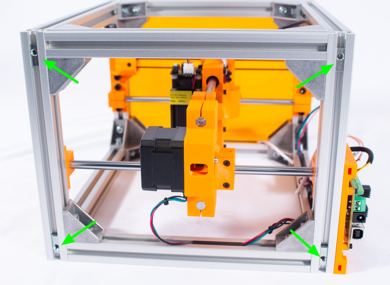
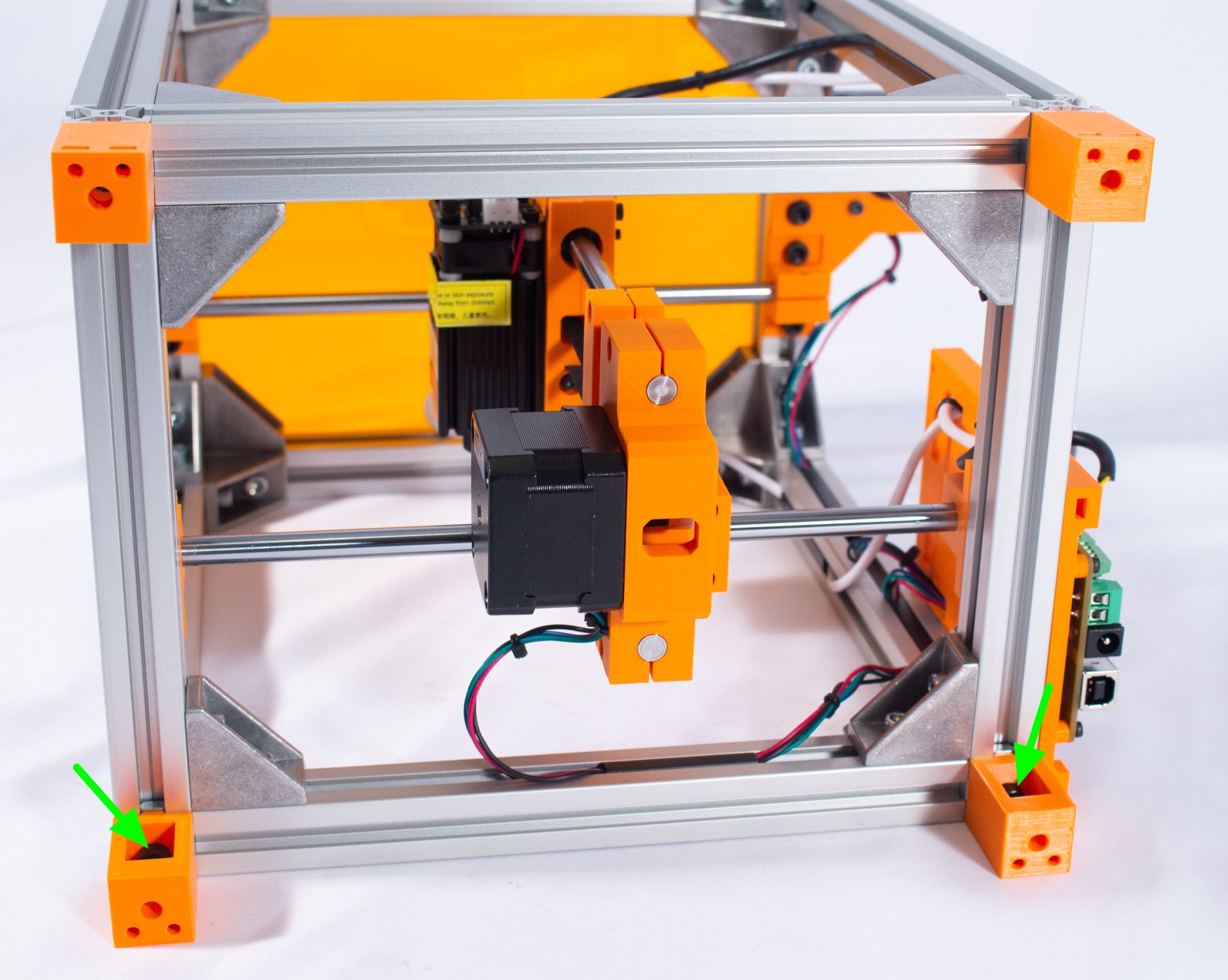
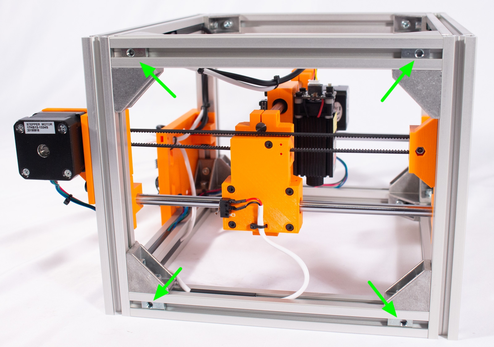
- Insert 4 of the spring nuts, as shown, into the extrusion channels on the right side.
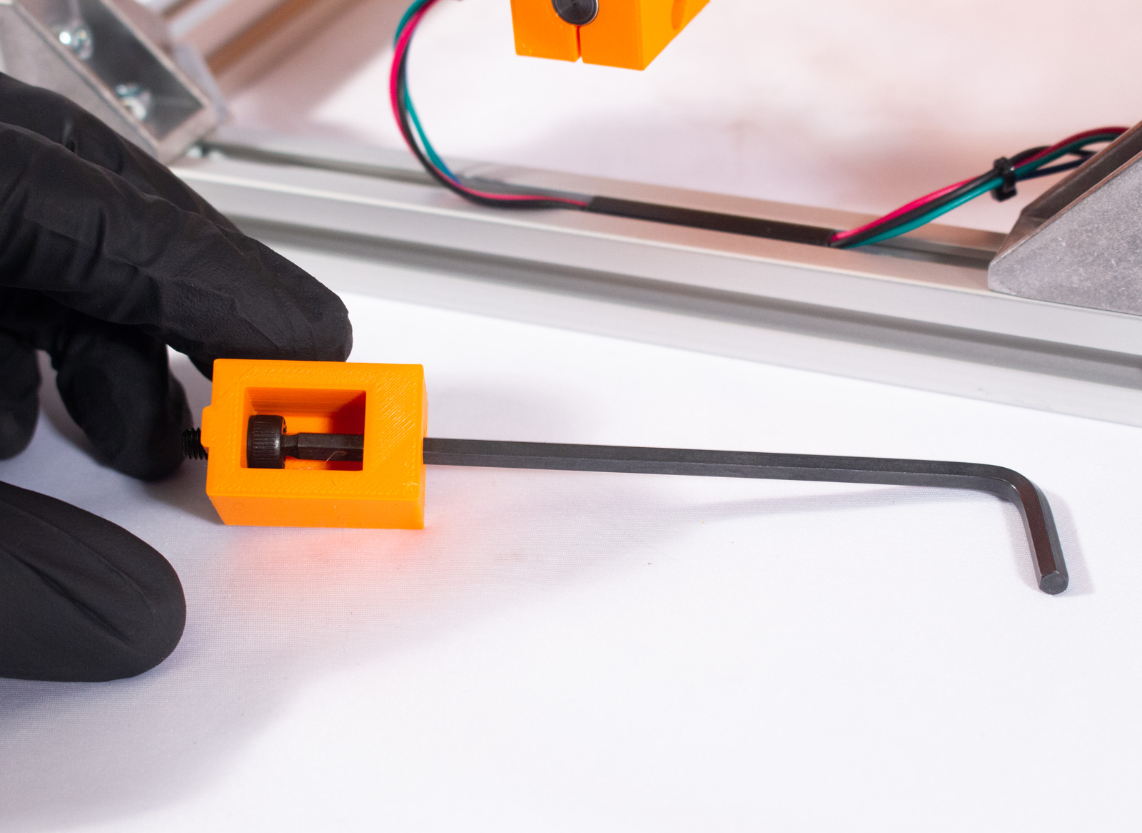
- Take each of the x4_ExtensionBracket parts and insert an M5x10mm bolt into the cavity, then insert the 4mm hex key through the front hole and use that to get the bolt into the hole on the other side, as shown.
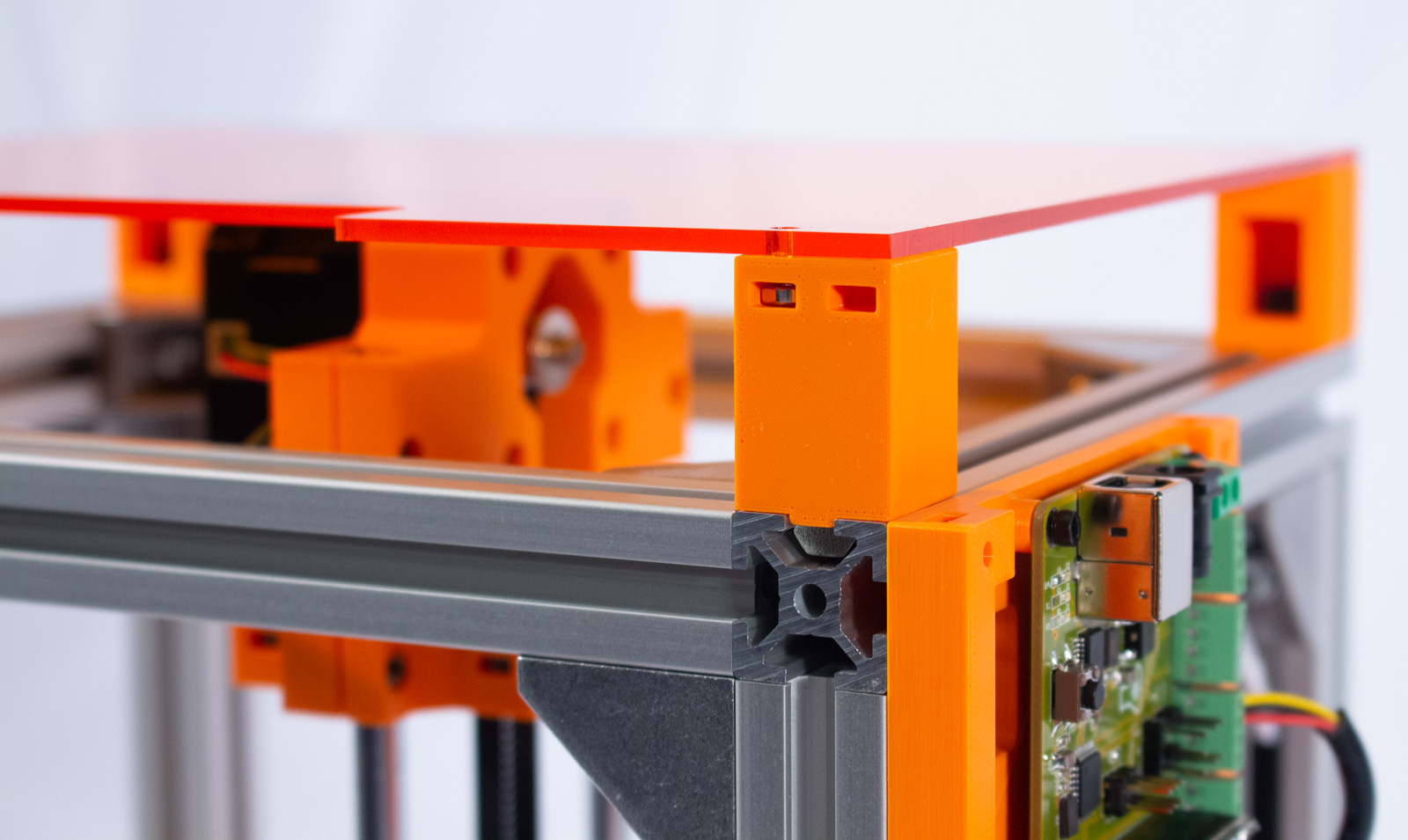
- With the hex key still inserted, mount the bracket onto one corner of the right side. For each, you want the open cavity to be facing in, and the two holes and M3 nut slots facing out, as shown. The tabs should fit into the channel and each bracket needs to be flush with the end of the vertical extrusions.
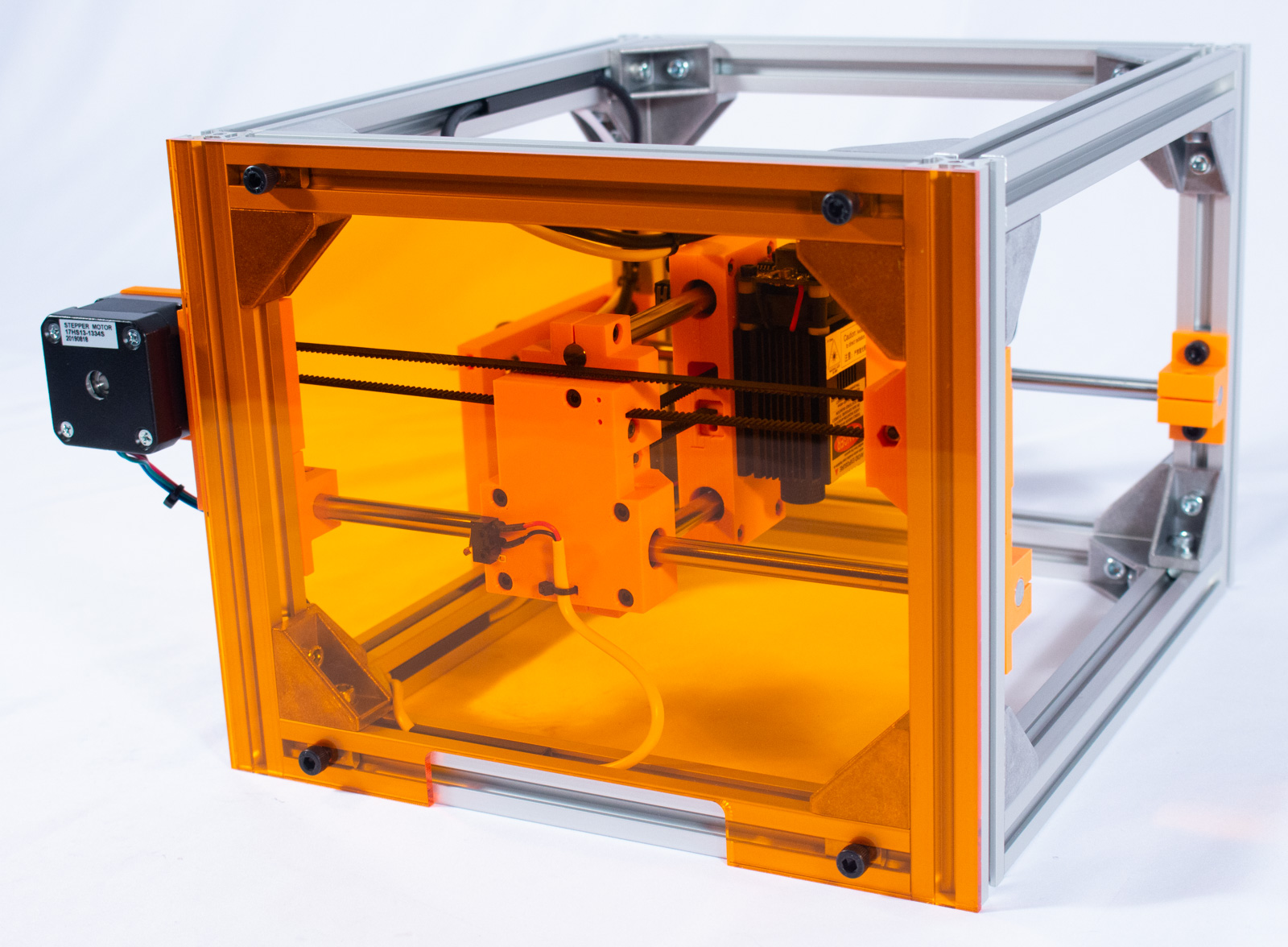
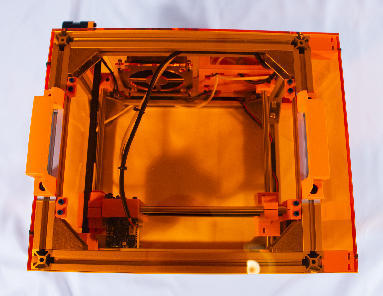
Right Panel
- Carefully move the motion carriage to the left side of the machine and then flip the whole machine so it is resting on the left side.
- Remove the paper backing from both sides of RightPanel.
- Insert an M3 nut into the inner slot on each of the extension brackets.
- Mount RightPanel to the brackets with the M3x10mm bolts. Do not tighten them excessively as you may crack the acrylic.
Front & Top Panels
Components
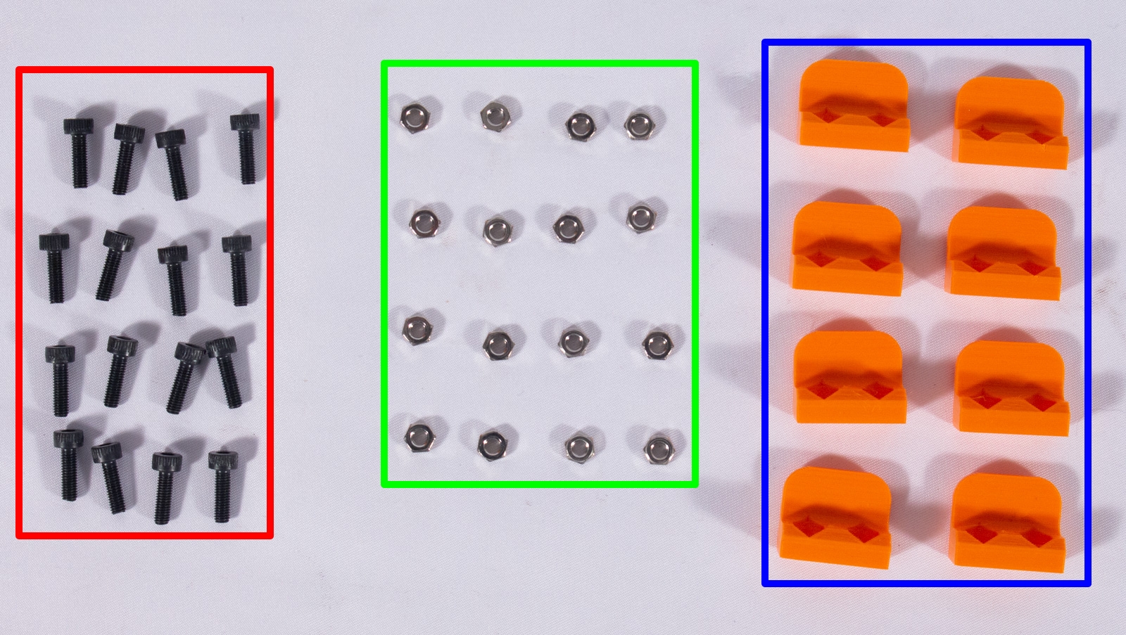
- x8_PanelClips (x8)
- FrontPanel (x1)
- TopPanel (x1)
- M3 nut (x16)
- M3x10mm bolt (x16)
Front Panel

- Remove the paper backing from both sides of FrontPanel.
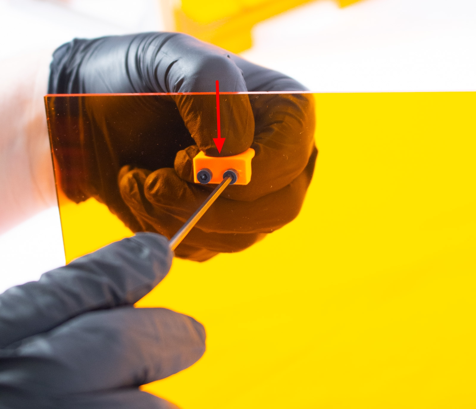
- One at a time, take one of x8_PanelClips and insert an M3 nut into each of the hexagonal recesses.
- Note: The holes in FrontPanel are shifted towards the left of the panel when looking at it from the front. Use this to ensure you install the clips on the correct side.
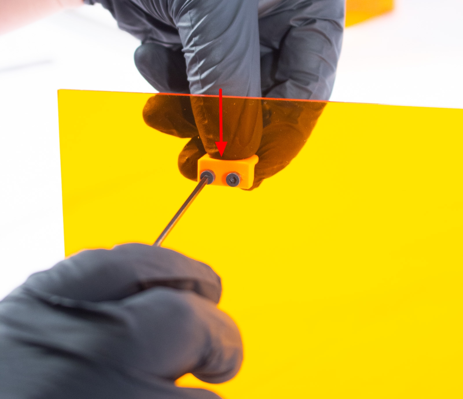
- While holding the nuts in with a finger, use 2 M3x10mm bolts to attach the clip to the back of FrontPanel panel with the bolts on the side facing the center of the panel, as shown. Do not tighten fully yet.
- Repeat this for the other 3 clips and, again, make sure the bolts and nuts are oriented towards the center and the bump on the clips oriented out (they will be locking into the extrusions).
- Once all are lightly on, one at a time, tighten the bolts while pressing the clip towards the center of the panel (this will ensure proper fit).
- You should now be able to snap the panel into the front, as shown. If it does not quite fit, loosen the bolts on any clip that looks to be causing the issue, check again that the clip is pushed towards the center, and tighten again.
Top Panel
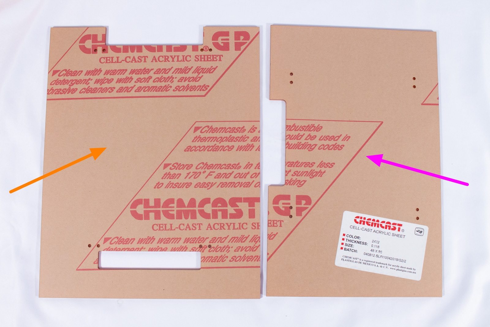
- Remove the paper backing from both sides of TopPanel.
- Follow the same process as for FrontPanel, remembering that the side that expands beyond the cutout is the right side, as shown. This panel is symmetric otherwise and there is no specific front or back.
- Snap the panel onto the top, as shown.
Back Panel
Components
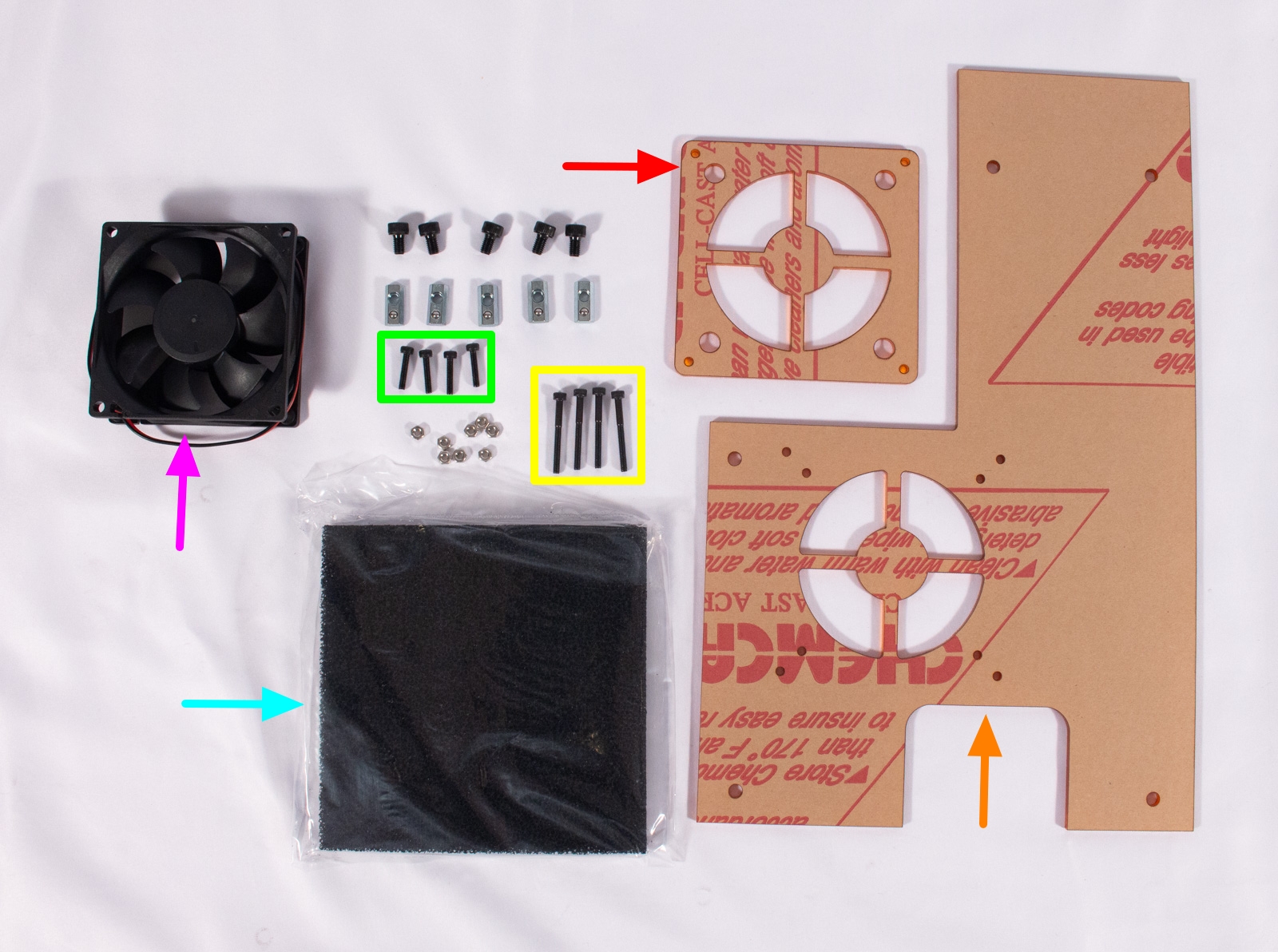
- BackPanel
- FilterHolder
- M5x8mm bolt (x5)
- Post Assembly Spring Nut (x5)
- M3 nut (x8)
- M3x14mm bolt (x4)
- M3x30mm bolt (x4)
- 80mmx25mm 12V Fan
- Carbon Filter
Fan
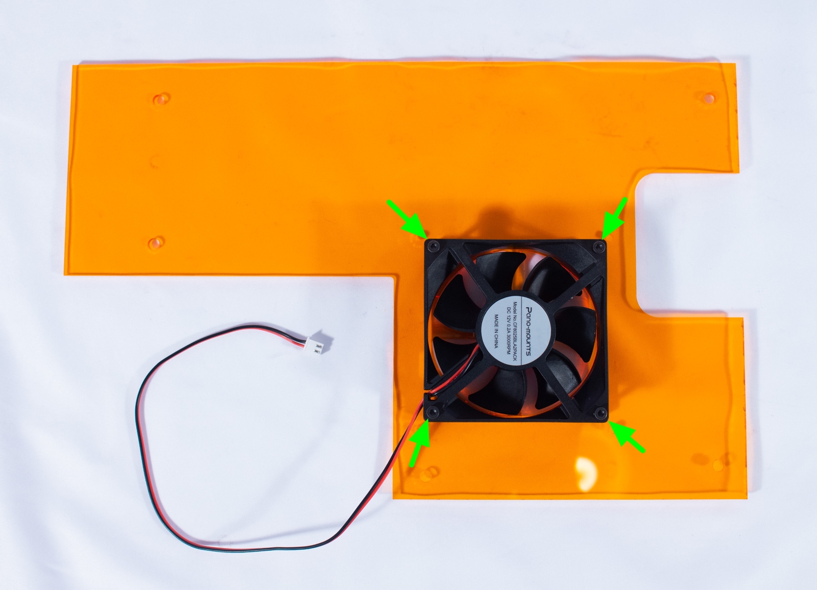
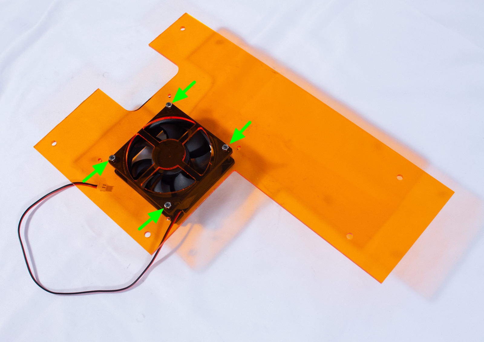
- Remove the paper backing from both sides of BackPanel.
- Determine which direction the fan blows (there's often an arrow on the side) and orient it on BackPanel so that air will flow out and with the power wires in the lower corner on the controller side.
- Insert the 4 M3x30mm bolts through the fan body and BackPanel
- Flip everything over and secure the fan with 4 M3 nuts and tighten lightly.
Filter
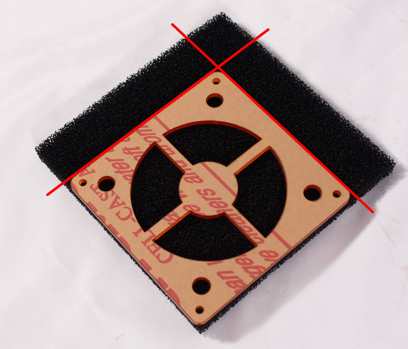
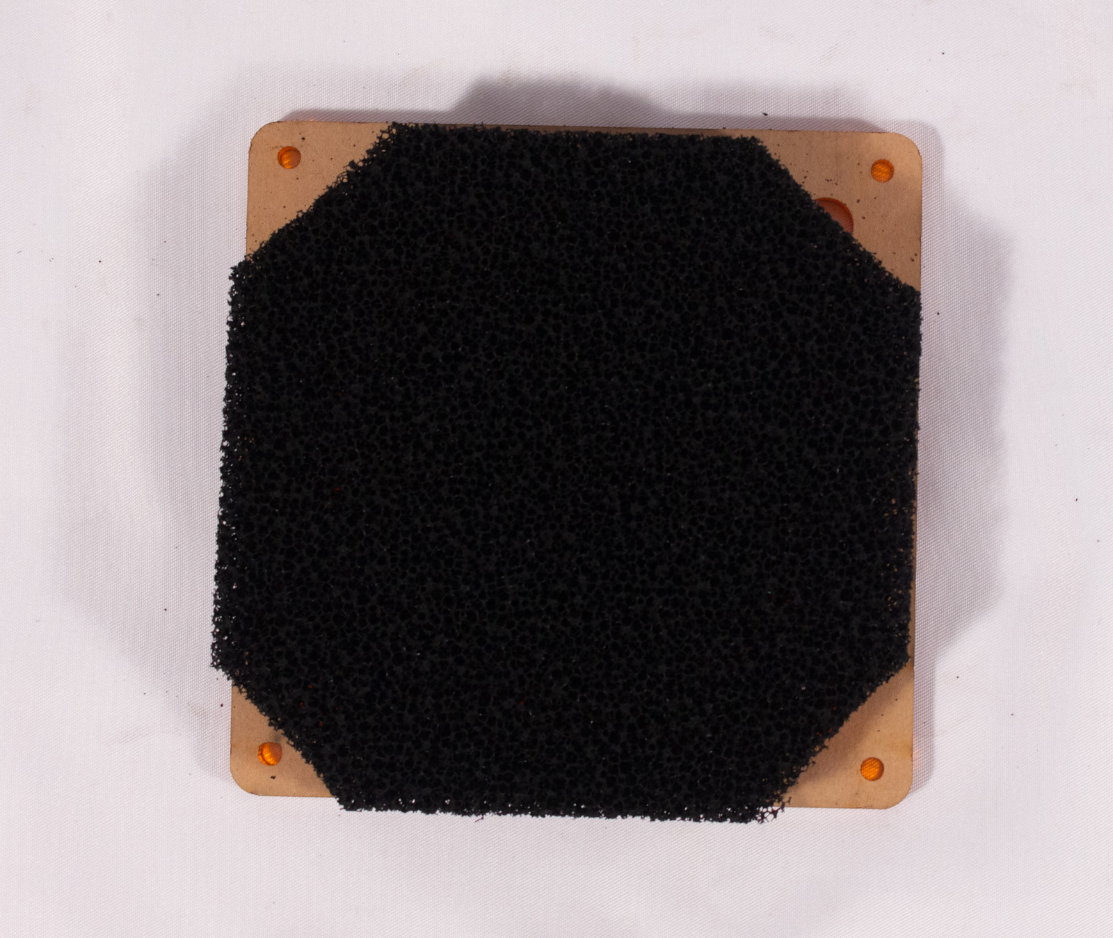
- If necessary, use FilterHolder as a template to cut the carbon filter down to the correct size. First cut it to the exact dimensions as FilterHolder and then cut off each of the 4 corners so that the 4 corner holes are no longer blocked.
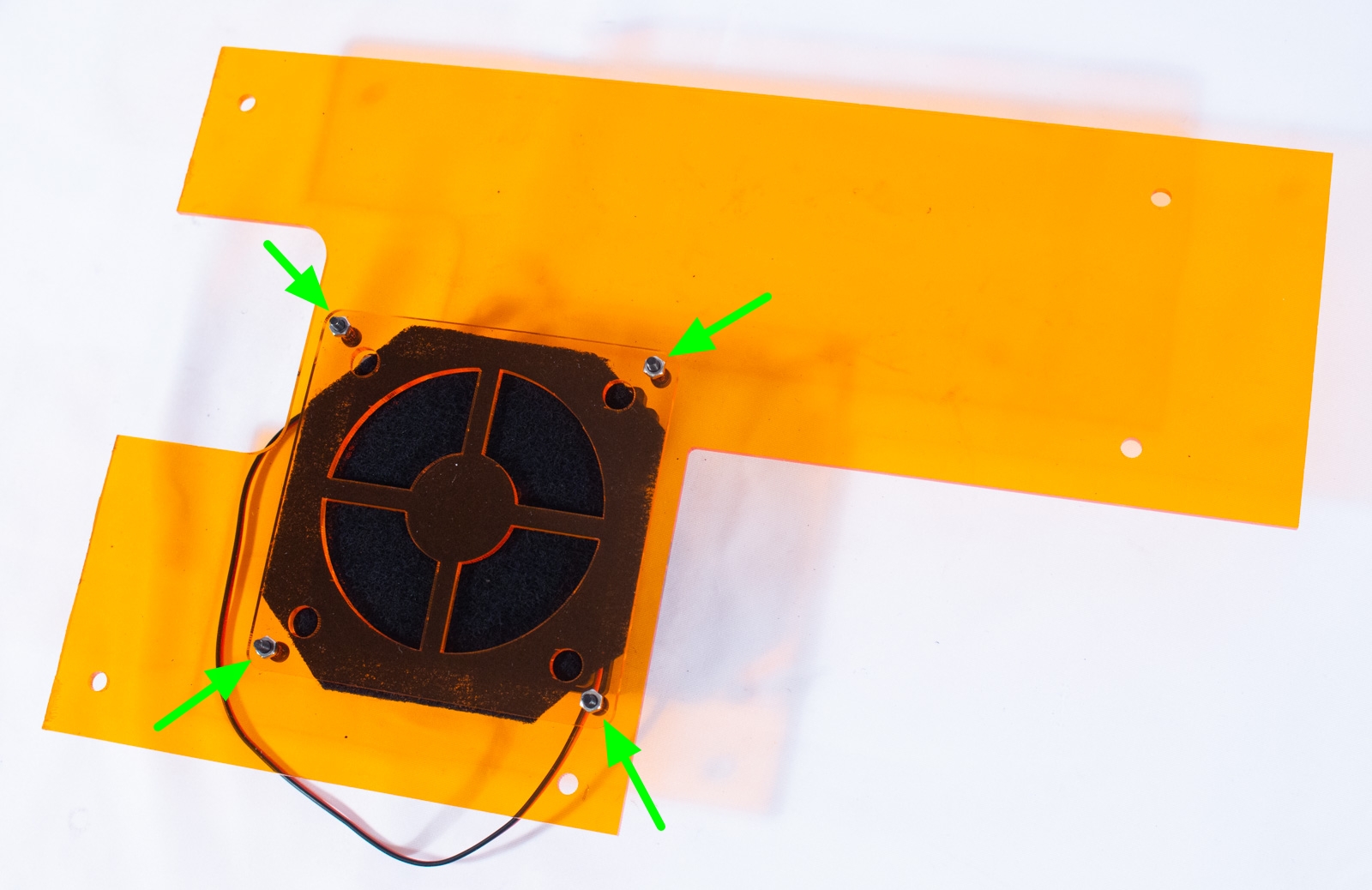
- Insert the 4 M3x14mm bolts in from the back of BackPanel then place the filter in between those bolts, and sandwich FilterHolder on top of the filter.
- Use 4 M3 nuts to tighten FilterHolder down. Just enough to hold it in place.
Mount Back Panel

- Insert the 5 spring nuts, as shown.
- Place BackPanel up against the machine and use one of the smaller hex keys to ensure all the nuts are positioned correctly beneath the holes.
- Insert the 5 M5x8mm bolts and tighten lightly.
Connect Fan
If you happened to provide your own fan it could be 5V instead of 12V. In that case just connect to an appropriate 5V source on the controller.
- You may have to take the controller cover off if you installed it already.
- Attach the fan wires to the the 12V power terminal. On the Platypus there is an "Aux Power" terminal with 12V and Ground connections just for this purpose.
- Remember: Black is ground and 12V will be either Red or Yellow.
Handles
Components

- x2_Handles (x2)
- M5x10mm bolt (x4)
- Post Assembly Spring Nut (x4)
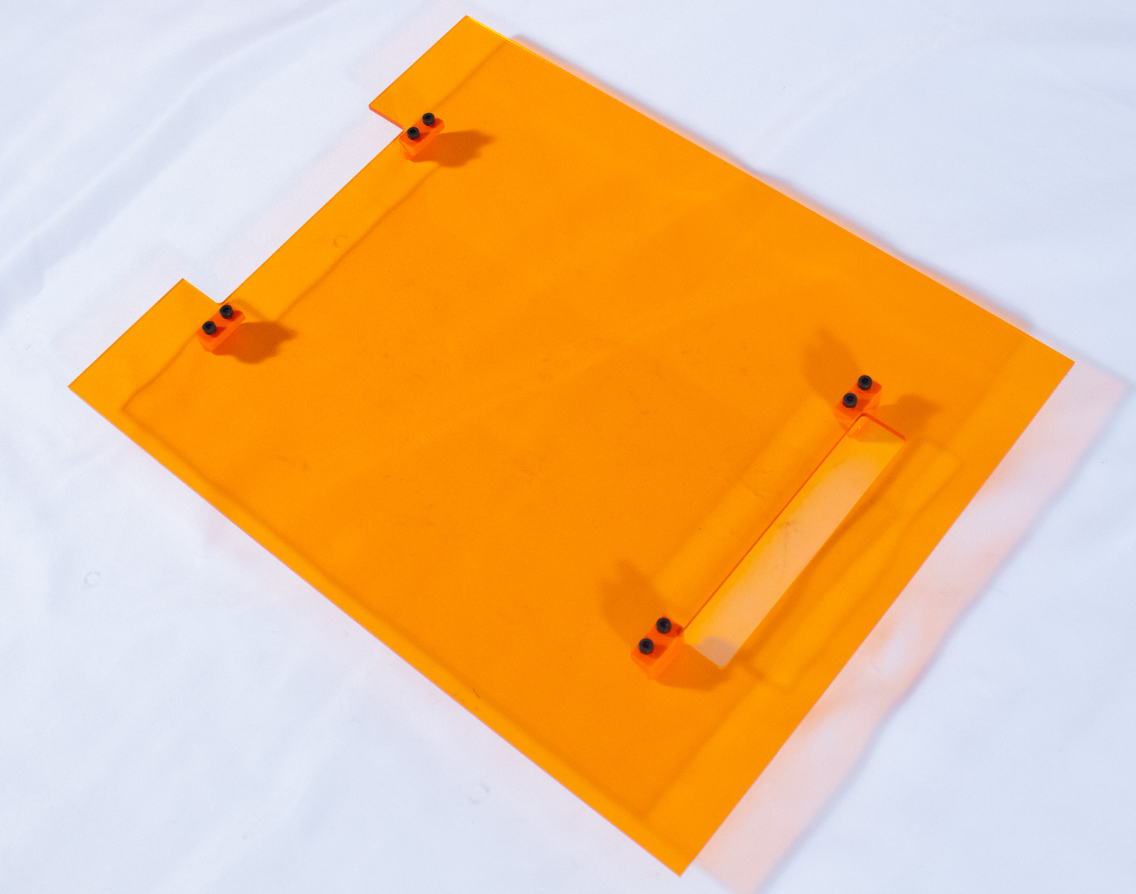
Install Handles
- Insert the 4 spring nuts, as shown.
- Insert an M4x10mm bolt into each of the holes on the handles.
- Match up the bolts with the spring nuts, ensure they are centered between the cut outs in TopPanel and tighten the bolts.
Targeting Frame
This step is optional and, as of the writing of this guide, is only available if you are using one of the recommended EleksMaker EL01 or FB03 laser modules (or another module that is 33mm x 33mm). The targeting frame panel provided will ONLY work with laser modules of that size!
Components
- x4_Feet (x4)
- TargetingFrame_33x33 (x1)
- M5x10mm bolt (x4)
- Post Assembly Spring Nut (x4)
Assembly
- Flip the machine onto the left side, being careful to support the carriage as it falls to that side.
- Remove the paper backing from the TargetingFrame_33x33 acrylic panel on both sides.
- Insert the 4 spring nuts, as shown.
- The engraved tick marks must face up into the machine when assembled and the square hole is offset towards the front of the machine. Place the panel up against the bottom of the machine in the described orientation. Use a hex key to reposition the spring nuts behind each of the holes.
- With each of 4x_Feet insert an M5x10 bolt and then insert that through the panel and start to screw into the spring nut.
- The holes in the feet are off-center. Make sure that the edge of each is flush with the edge of the acrylic and then tighten the bolt.
Controller Cover
Now that you have the fan wired in you may not put the enclosure cover on.
Components
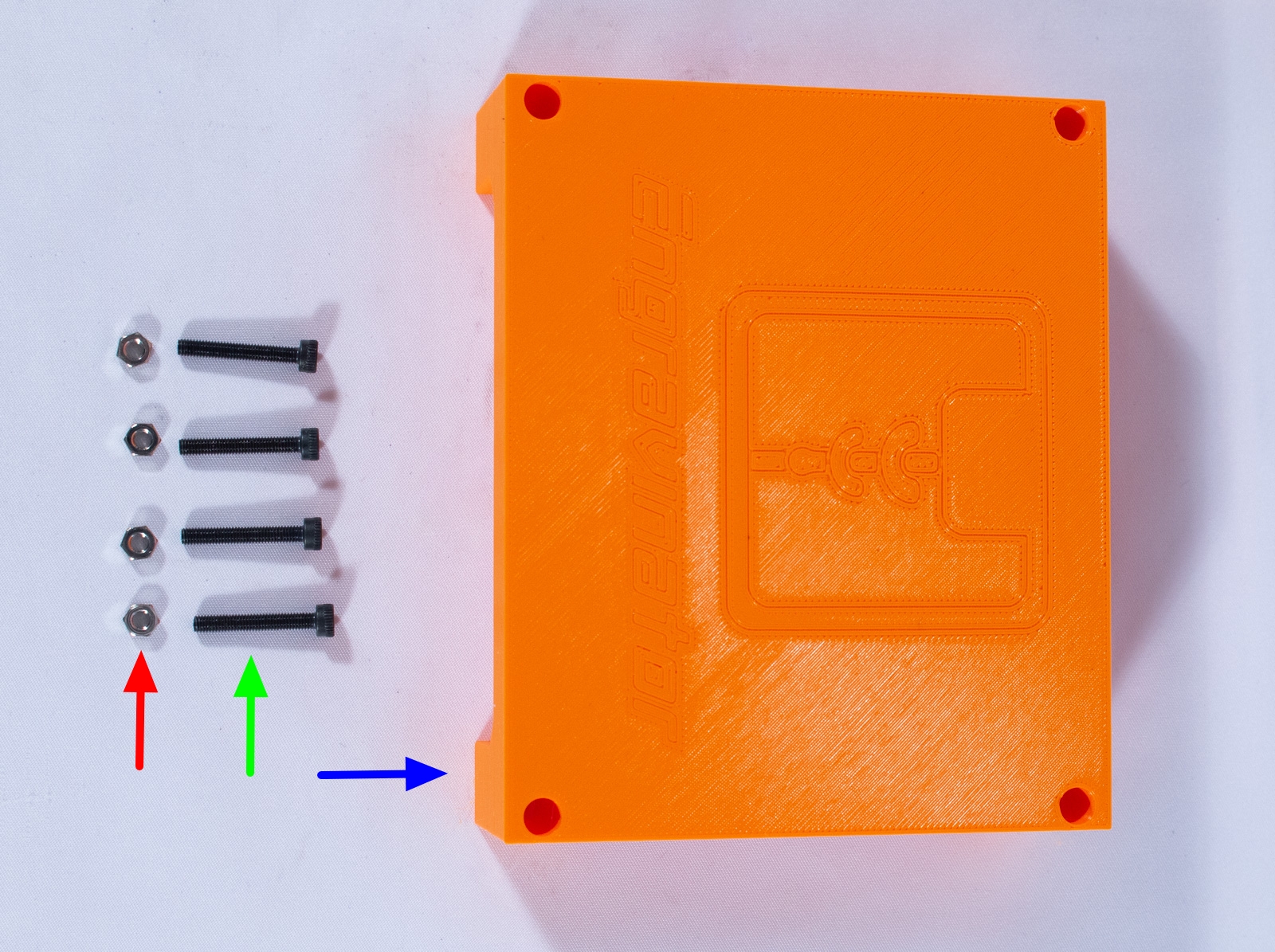
- ControllerCover (x1)
- M3x20mm bolt (x4)
- M3 nut (x4)
Assembly
- Flip the Engravinator up onto its front face.
- Insert an M3 nut into each of the slots on the controller base plate.
- Insert an M3x30mm bolt into each of the holes in the cover and align with the holes in the base plate.
- Tighten all 4 bolts to secure the cover.
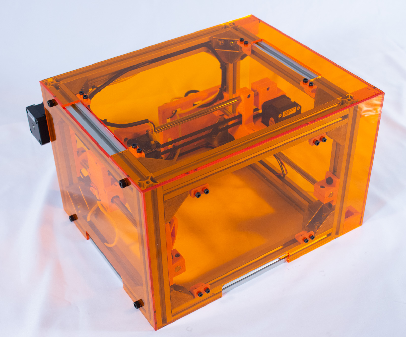
Treat Yourself!
That's it! You are done! Have a cookie and have fun! But safe fun ;)
Head on over to the next section to learn a little about actually using your Engravinator!